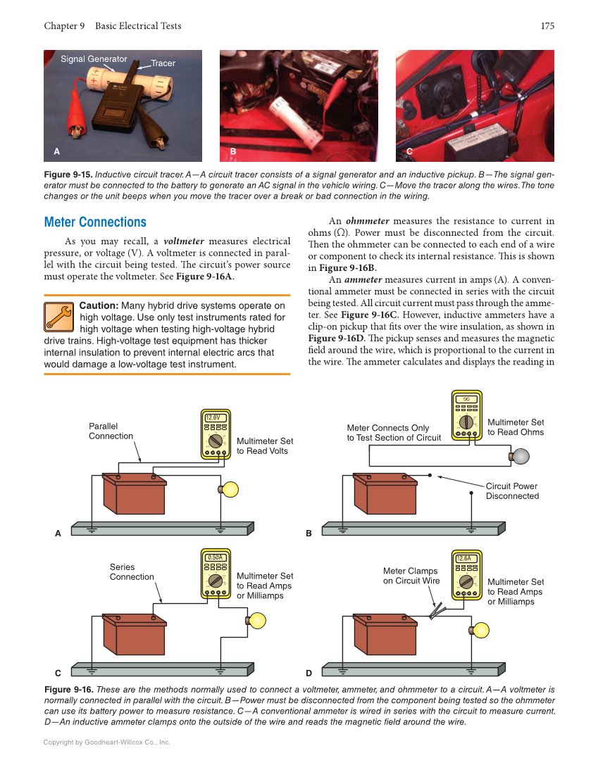
Chapter 9 Basic Electrical Tests 175 Copyright by Goodheart-Willcox Co., Inc. Meter Connections As you may recall, a voltmeter measures electrical pressure, or voltage (V). A voltmeter is connected in paral- lel with the circuit being tested. Th e circuit’s power source must operate the voltmeter. See Figure 9-16A. Caution: Many hybrid drive systems operate on high voltage. Use only test instruments rated for high voltage when testing high-voltage hybrid drive trains. High-voltage test equipment has thicker internal insulation to prevent internal electric arcs that would damage a low-voltage test instrument. An ohmmeter measures the resistance to current in ohms (Ω). Power must be disconnected from the circuit. Th en the ohmmeter can be connected to each end of a wire or component to check its internal resistance. Th is is shown in Figure 9-16B. An ammeter measures current in amps (A). A conven- tional ammeter must be connected in series with the circuit being tested. All circuit current must pass through the amme- ter. See Figure 9-16C. However, inductive ammeters have a clip-on pickup that fi ts over the wire insulation, as shown in Figure 9-16D. Th e pickup senses and measures the magnetic fi eld around the wire, which is proportional to the current in the wire. Th e ammeter calculates and displays the reading in Figure 9-15. Inductive circuit tracer. A—A circuit tracer consists of a signal generator and an inductive pickup. B—The signal gen- erator must be connected to the battery to generate an AC signal in the vehicle wiring. C—Move the tracer along the wires. The tone changes or the unit beeps when you move the tracer over a break or bad connection in the wiring. Tracer Signal Generator A B C Figure 9-16. These are the methods normally used to connect a voltmeter, ammeter, and ohmmeter to a circuit. A—A voltmeter is normally connected in parallel with the circuit. B—Power must be disconnected from the component being tested so the ohmmeter can use its battery power to measure resistance. C—A conventional ammeter is wired in series with the circuit to measure current. D—An inductive ammeter clamps onto the outside of the wire and reads the magnetic field around the wire. Parallel Connection Multimeter Set to Read Volts Circuit Power Disconnected Multimeter Set to Read Ohms Series Connection Multimeter Set to Read Amps or Milliamps Meter Connects Only to Test Section of Circuit Meter Clamps on Circuit Wire Multimeter Set to Read Amps or Milliamps ~V OFF V Ω mA A mA A ~ ~V OFF V Ω mA A mA A ~ ~V OFF V Ω mA A mA A ~ 12.6V 0.50A ~V OFF V Ω mA A mA A ~ 12.6A A C B D
