340
AutoCAD and Its Applications—Basics
Copyright Goodheart-Willcox Co., Inc.
If you select the same point for the fi rst and second break points, the
BREAK
command
splits the object into separate segments without removing a portion. At the
Specify second
break point or [First point]:
prompt, use object snaps or coordinate entry, or enter
@
to select
the same coordinates as the fi rst break point. See Figure 11-11. To automate the process, use
the
Break at Point
command instead of the standard
BREAK
command.
Select points in a counterclockwise direction when breaking circular objects to
ensure that you remove the correct portion of the object. See Figure 11-12. Notice in
Figure 11-12 that you can break off the end of an open object by picking the fi rst point
on the object and the second point slightly beyond the end to be cut off. AutoCAD
selects the endpoint nearest the point you pick.
PROFESSIONAL TIP PROFESSIONAL TIP
Use object snaps to pick a point accurately when using the
First point
option of the
BREAK
command. However, it may be necessary to turn
running object snaps off if they confl ict with points you try to pick.
Exercise 11-5
Complete the exercise on the companion website.
www.g-wlearning.com/CAD
Ribbon
Home
Modify
Break at Point
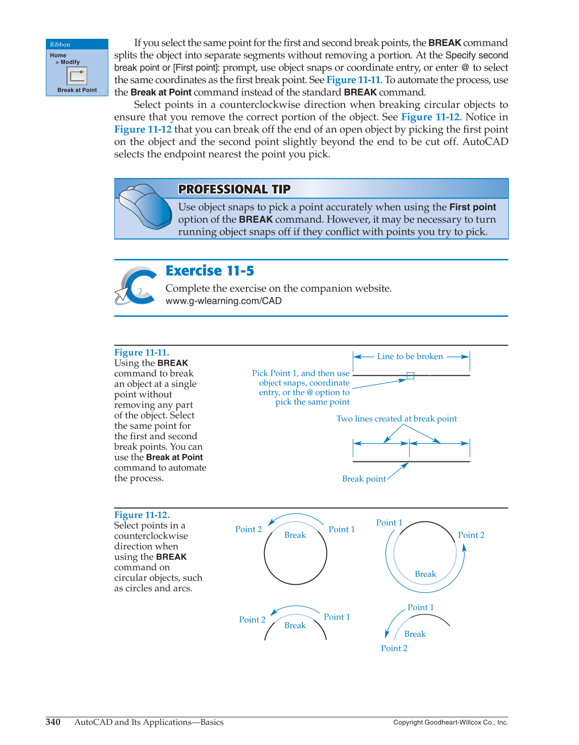
Figure 11-11.
Using the
BREAK
command to break
an object at a single
point without
removing any part
of the object. Select
the same point for
the first and second
break points. You can
use the
Break at Point
command to automate
the process.
Two lines created at break point
Line to be broken
Break point
Pick Point 1, and then use
object snaps, coordinate
entry, or the @ option to
pick the same point
Figure 11-12.
Select points in a
counterclockwise
direction when
using the
BREAK
command on
circular objects, such
as circles and arcs.
Point 2
Break
Break
Break
Break
Point 2
Point 2
Point 2
Point 1
Point 1
Point 1
Point 1