Chapter 8 Creating and Working with Solid Model Features
195
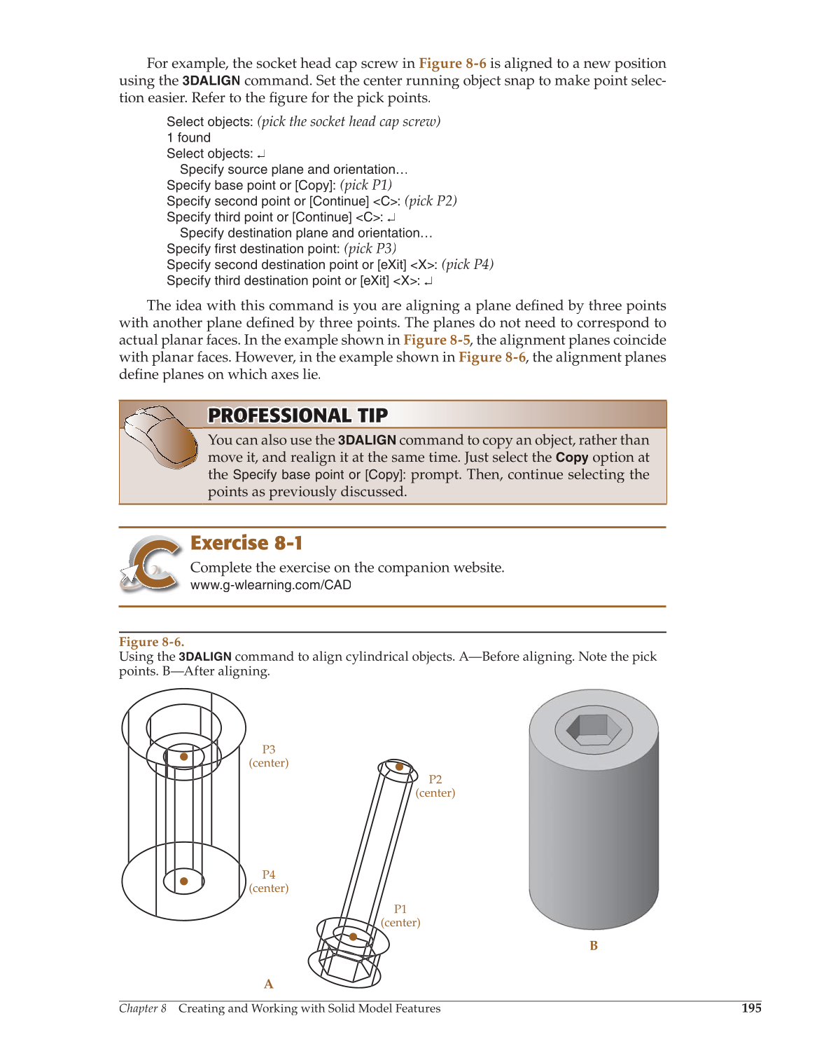
For example, the socket head cap screw in Figure 8-6 is aligned to a new position
using the
3DALIGN
command. Set the center running object snap to make point selec-
tion easier. Refer to the fi gure for the pick points. fi
Select objects:
(pick the socket head cap screw)
1 found
Select objects: ↵
Specify source plane and orientation…
Specify base point or [Copy]:
(pick P1)
Specify second point or [Continue] C:
(pick P2)
Specify third point or [Continue] C: ↵
Specify destination plane and orientation…
Specify first destination point:
(pick P3)
Specify second destination point or [eXit] X:
(pick P4)
Specify third destination point or [eXit] X: ↵
The idea with this command is you are aligning a plane defi by three points fined
with another plane defi by three points. The planes do not need to correspond to fined
actual planar faces. In the example shown in Figure 8-5, the alignment planes coincide
with planar faces. However, in the example shown in Figure 8-6, the alignment planes
defi planes on which axes lie. fine
Exercise 8-1
Complete the exercise on the companion website.
www.g-wlearning.com/CAD
PROFESSIONAL O NA TIP T P PROF RO FE S S IO N A L T I O NA AL T I P TI P
You can also use the
3DALIGN
command to copy an object, rather than
move it, and realign it at the same time. Just select the
Copy
option at
the
Specify base point or [Copy]:
prompt. Then, continue selecting the
points as previously discussed.
Figure 8-6.
Using the
3DALIGN
command to align cylindrical objects. A—Before aligning. Note the pick
points. B—After aligning.
B
A
P4
(center)
P3
(center)
P1
(center)
P2
(center)