358
AutoCAD and Its Applications—Basics
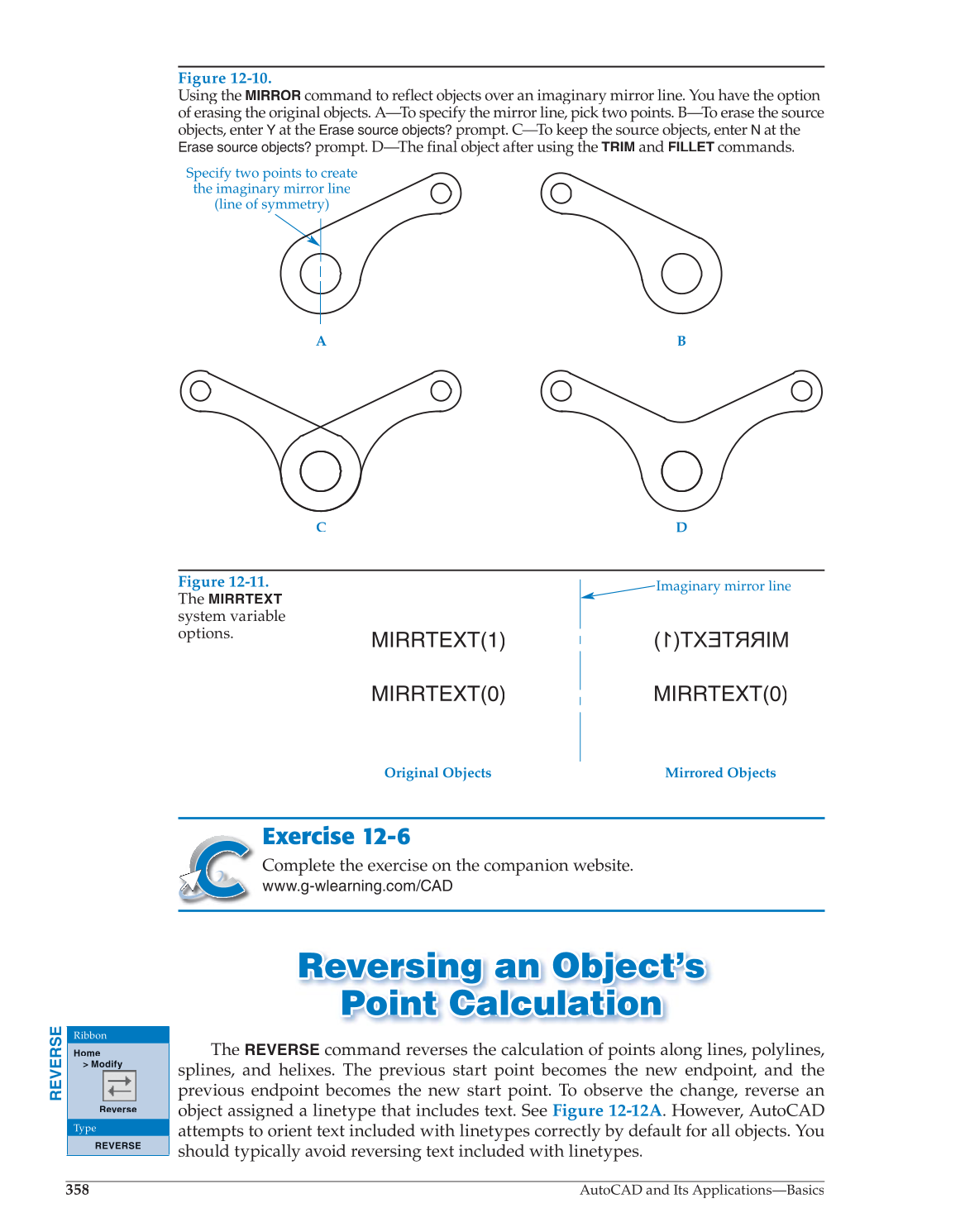
Figure 12-10.
Using the
MIRROR
command to reflect objects over an imaginary mirror line. You have the option
of erasing the original objects. A—To specify the mirror line, pick two points. B—To erase the source
objects, enter
Y
at the
Y Erase source objects?
prompt. C—To keep the source objects, enter
N
at the
Erase source objects?
prompt. D—The final object after using the
TRIM
and
FILLET
commands.
T
C D
A B
Specify two points to create
the imaginary mirror line
(line of symmetry)
Figure 12-11.
The
MIRRTEXT
system variable
options.
Mirrored Objects Original Objects
Imaginary mirror line
MIRRTEXT(1)
MIRRTEXT(0) MIRRTEXT(0)
Exercise 12-6
Complete the exercise on the companion website.
www.g-wlearning.com/CAD
Reversing an Object’s Rever s ing a n Object’ s
Point Calculation Point C a lcul a tion
The
REVERSE
command reverses the calculation of points along lines, polylines,
splines, and helixes. The previous start point becomes the new endpoint, and the
previous endpoint becomes the new start point. To observe the change, reverse an
object assigned a linetype that includes text. See Figure 12-12A. However, AutoCAD
attempts to orient text included with linetypes correctly by default for all objects. You
should typically avoid reversing text included with linetypes.
REVERSE
Ribbon
Home
Modify
Reverse
Type
REVERSE