Chapter 8 Creating and Working with Solid Model Features
215
Using the
CHAMFER
command to chamfer a hole is shown in Figure 8-21A. In
Figure 8-21B, the cylinder is unioned to the base in order to create the chamfer at the
intersection. The ends of the cylinder in Figure 8-21B are chamfered by fi rst picking fi
a vertical isoline on the cylindrical face to define the base surface. Then, the top edge fi
is selected, followed by the intersection edge. The following command sequence is
illustrated in Figure 8-21A.
(TRIM mode) Current chamfer Dist1 = 1.0000, Dist2 = 1.0000
Select first line or [Undo/Polyline/Distance/Angle/Trim/mEthod/Multiple]:
(select a top
edge)
Base surface selection...
Enter surface selection option [Next/OK (current)] OK:
(select
Next
if the top sur-
face is not selected or press [Enter])
Specify base surface chamfer distance or [Expression] 1.0000: .125↵
Specify other surface chamfer distance or [Expression] 1.0000: .125↵
Select an edge or [Loop]:
(select the hole diameter edge)
Select an edge or [Loop]: ↵
NOTE OT OT TE
Editing a fillet or chamfer is discussed in Chapter 11. The fi
SOLIDEDIT
command discussed in Chapter 12 can also be used to edit a fillet or fi
chamfer.
Exercise 8-8
Complete the exercise on the companion website.
www.g-wlearning.com/CAD
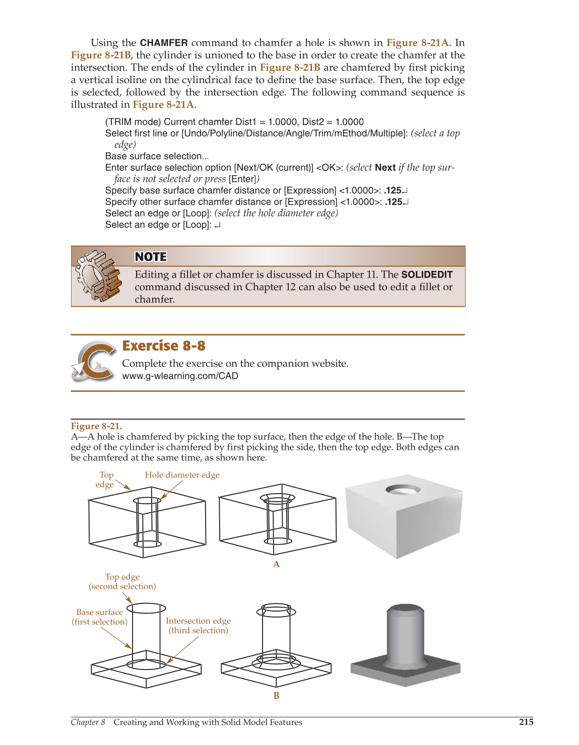
Figure 8-21.
A—A hole is chamfered by picking the top surface, then the edge of the hole. B—The top
edge of the cylinder is chamfered by first picking the side, then the top edge. Both edges can
be chamfered at the same time, as shown here.
Top
edge
Hole diameter edge
A
B
Top edge
(second selection)
Base surface
(first selection)
Intersection edge
(third selection)