22
AutoCAD and Its Applications—Basics
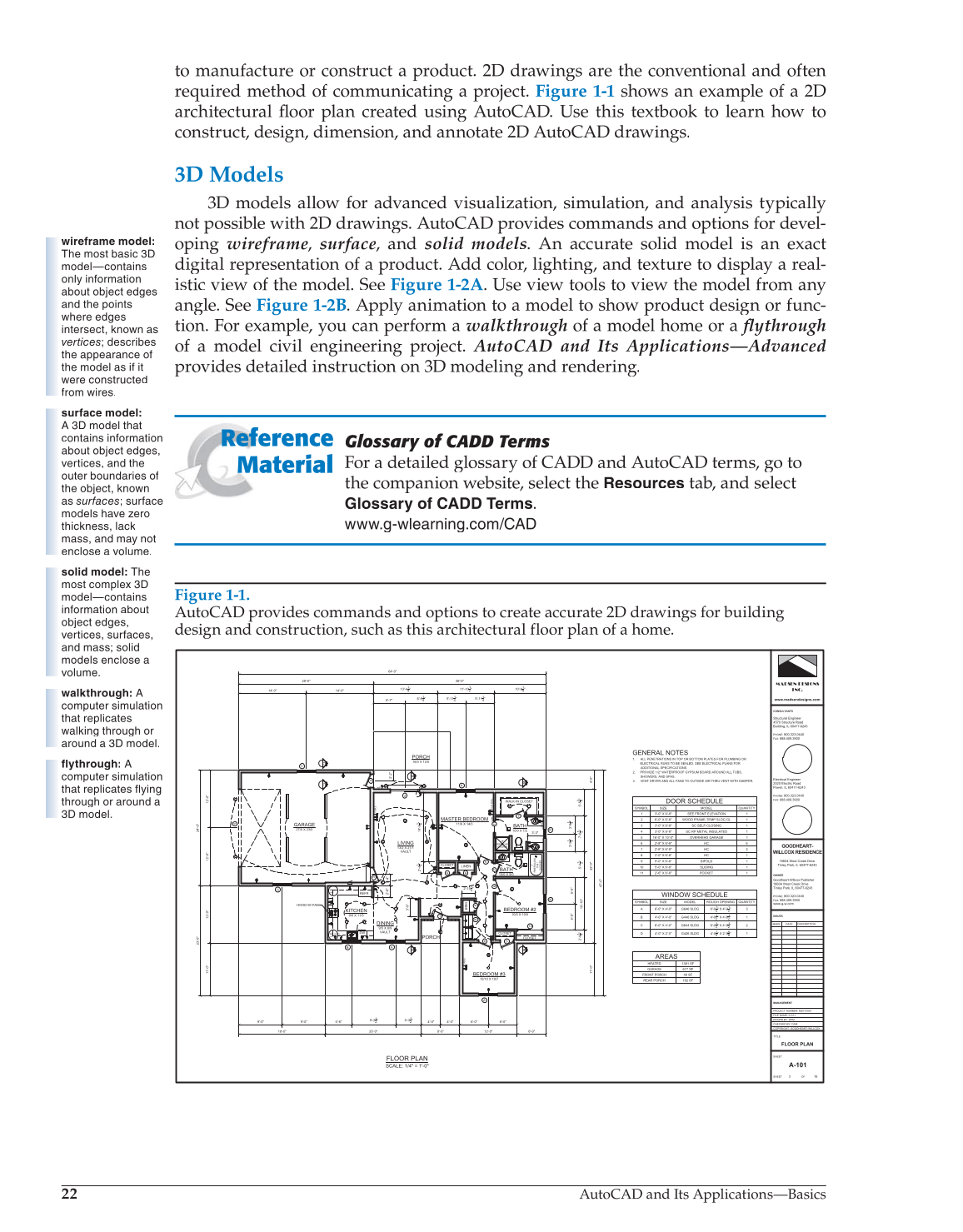
to manufacture or construct a product. 2D drawings are the conventional and often
required method of communicating a project. Figure 1-1 shows an example of a 2D
architectural floor plan created using AutoCAD. Use this textbook to learn how to fl
construct, design, dimension, and annotate 2D AutoCAD drawings.
3D Models
3D models allow for advanced visualization, simulation, and analysis typically
not possible with 2D drawings. AutoCAD provides commands and options for devel-
oping wireframe, surface, and solid models. An accurate solid model is an exact
digital representation of a product. Add color, lighting, and texture to display a real-
istic view of the model. See Figure 1-2A. Use view tools to view the model from any
angle. See Figure 1-2B. Apply animation to a model to show product design or func-
tion. For example, you can perform a walkthrough of a model home or a flythrough fl
of a model civil engineering project. AutoCAD and Its Applications—Advanced
provides detailed instruction on 3D modeling and rendering.
Glossary of CADD Terms
For a detailed glossary of CADD and AutoCAD terms, go to
the companion website, select the
Resources
tab, and select
Glossary of CADD
Terms.
www.g-wlearning.com/CAD
Reference
Material
wireframe model:
The most basic 3D
model—contains
only information
about object edges
and the points
where edges
intersect, known as
vertices; describes
the appearance of
the model as if it
were constructed
from wires.
surface model:
A 3D model that
contains information
about object edges,
vertices, and the
outer boundaries of
the object, known
as surfaces; surface
models have zero
thickness, lack
mass, and may not
enclose a volume.
solid model: The
most complex 3D
model—contains
information about
object edges,
vertices, surfaces,
and mass; solid
models enclose a
volume.
walkthrough: A
computer simulation
that replicates
walking through or
around a 3D model.
flythrough: A
computer simulation
that replicates flying
through or around a
3D model.
Figure 1-1.
AutoCAD provides commands and options to create accurate 2D drawings for building
design and construction, such as this architectural floor plan of a home.
REFR
LS
LS
28'-0"
4'-0"
32'-0"
11'-0"
6'-0" 12'-0" 8'-0" 20'-0" 18'-0"
23'-0"
24'-0"
36'-0"
47'-0"
64'-0"
VAULT
VAULT
14'-0" 14'-0"
6'-7"
6'-941" 5'-1141" 5'-1141"
2'-2"
5'-5
3 4
"
3'-9
1 4
"
3'-9
1
4
"
5'-4
1 2
"
5'-5"
5'-5"
2'-9
1 4
"
6'-0" 6'-0" 4'-0" 4'-0"
5'-321" 9'-221"
5'-6"
12'-0"
12'-0"
12'-0"
11'-0"
9'-0" 9'-0"
14'-5
1 4
"
2'-4
1 2
"
3'-9"
2'-6"
2'-4"
3'-3"
13'-441" 11'-1021" 10'-941"
7'-6
1 2
"
10'-10"
GFCI
SD
SD
SD
SD
WALK-IN CLOSET
CLOSET
CLOSET
CLOSET
LINEN
BRM
GFCI
WP
SD
2'-1021"
LFH
LFH
36"
FIBERGLASS
SHOWER
5'
FIBERGLASS
TUB
/
SHOWER
B A
A
A
D
A
C
4
2
7
11
6
7
6
8
6 6
9
6 6
10
1
3
5
A
A
B
B
C
C
6'
UP
WALL
CABLE
CABLE
CABLE
C
KITCHEN
9/0 X 11/5
DINING
9/5 X 8/9
LIVING
13/2 X 21/1
MASTER BEDROOM
11/6 X 14/3
BEDROOM #2
10/0 X 10/5
BEDROOM #3
10/10 X 10/7
GARAGE
27/0 X 23/0
PORCH
16/0 X 12/0
PORCH
BATH
10/0 X 7/2
BATH
10/0 X 5/0
HOOD W/ FAN
WINDOW SCHEDULE
SYMBOL SIZE MODEL ROUGH OPENING QUANTITY
A 6'-0" X 4'-0" G646 SLDG
6'-021"
X
4'-021"
3
B 4'-0" X 4'-0" G446 SLDG
4'-021"
X
4'-621"
1
C 6'-0" X 4'-0" G644 SLDG
6'-021"
X
4'-021"
2
D 4'-0" X 2'-0" G426 SLDG
4'-01"
2 X
2'-085"
1
DOOR SCHEDULE
SYMBOL SIZE MODEL QUANTITY
1 3'-0" X 6'-8" SEE FRONT ELEVATION 1
2 6'-0" X 6'-8" WOOD FRAME-TEMP SLDG GL 1
3 3'-0" X 6'-8" SC SELF-CLOSING 1
4 3'-0" X 6'-8" SC RP METAL INSULATED 1
5 16'-0" X 10'-0" OVERHEAD GARAGE 1
6 2'-8" X 6'-8" HC 6
7 2'-6" X 6'-8" HC 2
8 2'-0" X 6'-8" HC 1
9 5'-0" X 6'-8" BIFOLD 1
10 5'-0" X 6'-8" SLIDING 1
11 2'-6" X 6'-8" POCKET 1
GENERAL NOTES
1. ALL PENETRATIONS IN TOP OR BOTTOM PLATES FOR PLUMBING OR
ELECTRICAL RUNS TO BE SEALED. SEE ELECTRICAL PLANS FOR
ADDITIONAL SPECIFICATIONS.
2. PROVIDE 1/2" WATERPROOF GYPSUM BOARD AROUND ALL TUBS,
SHOWERS, AND SPAS.
3. VENT DRYER AND ALL FANS TO OUTSIDE AIR THRU VENT WITH DAMPER.
AREAS
HEATED 1381 SF
GARAGE 677 SF
FRONT PORCH 40 SF
REAR PORCH 192 SF
MADSEN DESIGNS
INC.
www.madsendesigns.com
CONSULTANTS
OWNER
ISSUES
COPYRIGHT: GOODHEART-WILLCOX
PROJECT NUMBER: MDI-10001
FILE NAME: A-101
DRAWN BY: DPM
CHECKED BY: DAM
TITLE
SHEET
3
OF
16
MARK DATE DESCRIPTION
MANAGEMENT
SHEET
PHONE:
800.323.0440
FAX:
888.409.3900
GOODHEART-
WILLCOX RESIDENCE
Structural Engineer
4570 Structure Road
Building, IL 60477-6243
PHONE:
800.323.0440
FAX:
888.409.3900
Electrical Engineer
2520 Electric Road
Power, IL 60477-6243
18604 West Creek Drive
Tinley Park, IL 60477-6243
PHONE:
800.323.0440
FAX:
888.409.3900
Goodheart-Willcox Publisher
18604 West Creek Drive
Tinley Park, IL 60477-6243
www.g-w.com
FLOOR PLAN
A-101
FLOOR PLAN
SCALE: 1/4" = 1'-0"