Chapter 1 Introduction to Three-Dimensional Modeling
25
Copyright Goodheart-Willcox Co., Inc.
As the cursor is moved over the view cube, individual faces, edges, and corners
are highlighted. If you pick one of the named faces on the view cube, that orthographic
plan view is displayed. However, the UCS is not changed. If you pick one of the corners,
an isometric view is displayed that corresponds to one of the preset isometric views. If
you pick an edge, an isometric view is displayed that looks at the edge you selected. If
you pick on the cube and drag the mouse, the view changes dynamically.
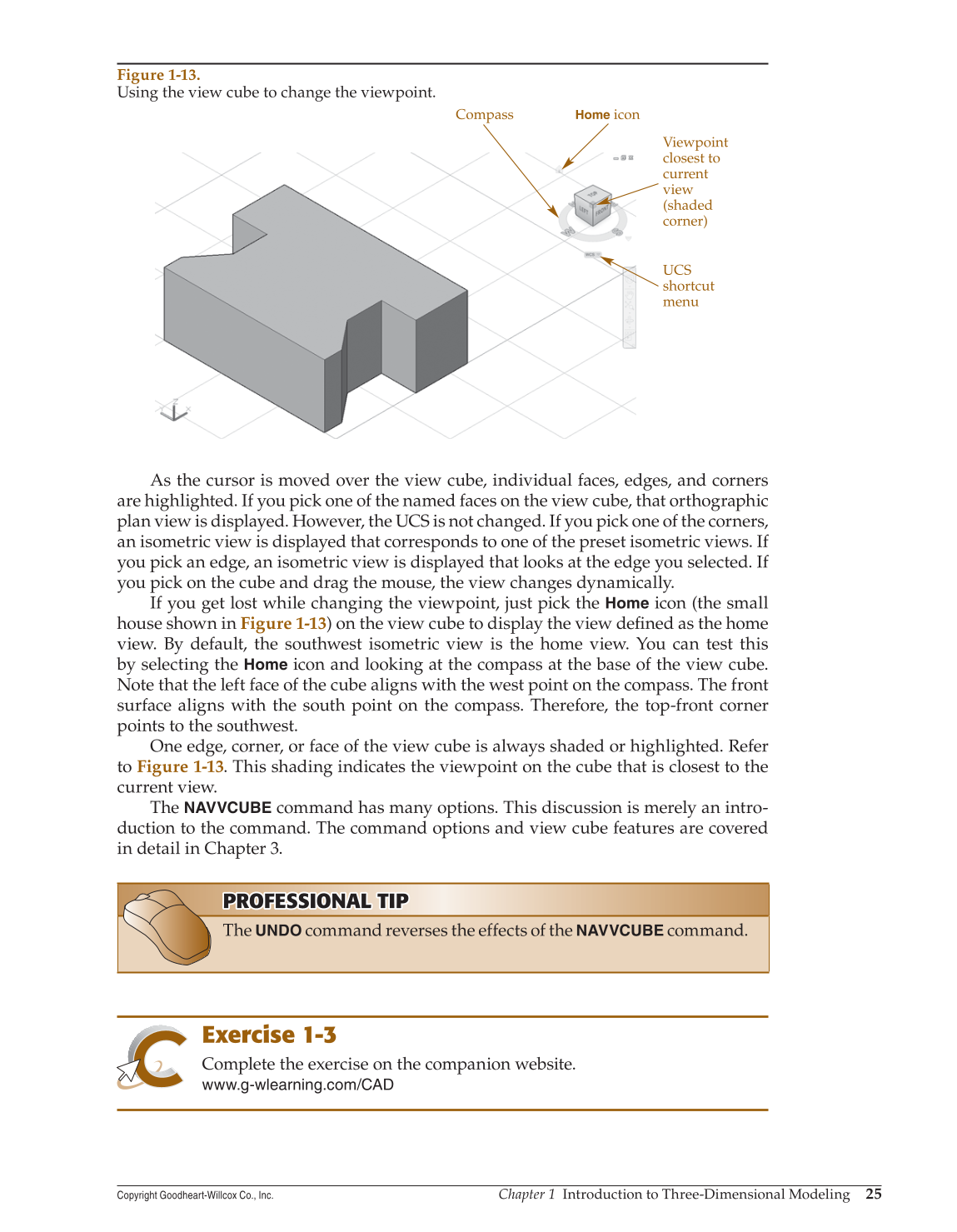
If you get lost while changing the viewpoint, just pick the
Home
icon (the small
house shown in Figure 1-13) on the view cube to display the view defi ned as the home
view. By default, the southwest isometric view is the home view. You can test this
by selecting the
Home
icon and looking at the compass at the base of the view cube.
Note that the left face of the cube aligns with the west point on the compass. The front
surface aligns with the south point on the compass. Therefore, the top-front corner
points to the southwest.
One edge, corner, or face of the view cube is always shaded or highlighted. Refer
to Figure 1-13. This shading indicates the viewpoint on the cube that is closest to the
current view.
The
NAVVCUBE
command has many options. This discussion is merely an intro-
duction to the command. The command options and view cube features are covered
in detail in Chapter 3.
PROFESSIONAL TIP PROFESSIONAL TIP
The
UNDO
command reverses the effects of the
NAVVCUBE
command.
Exercise 1-3
Complete the exercise on the companion website.
www.g-wlearning.com/CAD
UCS
shortcut
menu
Viewpoint
closest to
current
view
(shaded
corner)
Compass
Home
icon
Figure 1-13.
Using the view cube to change the viewpoint.