Chapter 8 Creating and Working with Solid Model Features
203
Copyright Goodheart-Willcox Co., Inc.
you specify. First, select the
SLICE
command, pick the object to slice, and press [Enter].
Next, enter the XY, YZ, or
ZX
option, depending on the primary plane to which the
cutting plane will be parallel. Then, pick a point on the cutting plane. Finally, pick the
side of the object to keep.
Three Points
Three points can be used to defi ne the cutting plane. This allows the cutting plane
to be aligned at any angle, similar to using the
Zaxis
option. See Figure 8-28. First,
select the
SLICE
command, pick the object to slice, and press [Enter]. Then, enter the
3points
option. Pick three points on the cutting plane and then select the side of the
object to keep.
Exercise 8-10
www.g-wlearning.com/CAD/
Complete the exercise on the companion website.
Removing Features Removing Features
Sometimes, it may be necessary to remove a feature that has been constructed. For
example, suppose you placed a R.5 fi llet on an object based on an engineering sketch.
Then, the design is changed to a R.25 fi llet. Subobject editing is the best technique to
accomplish this. Subobject editing is covered in Chapter 11.
Note
UCS
orientation
A B
C D
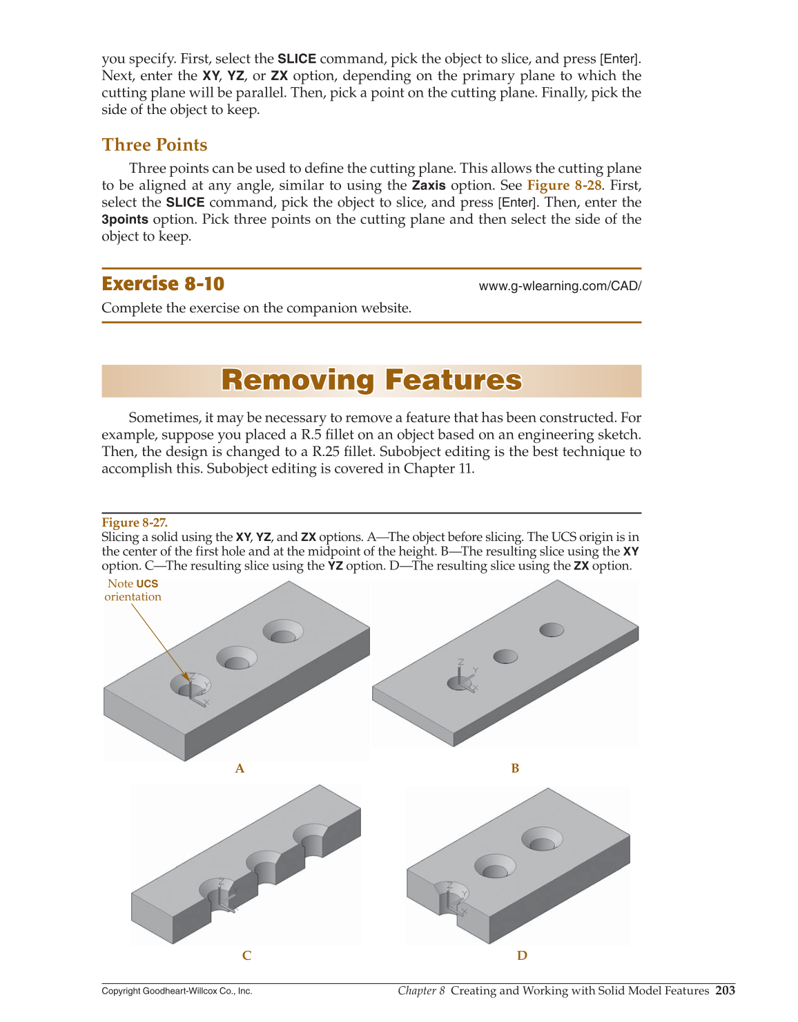
Figure 8-27.
Slicing a solid using the XY, YZ, and
ZX
options. A—The object before slicing. The UCS origin is in
the center of the first hole and at the midpoint of the height. B—The resulting slice using the
XY
option. C—The resulting slice using the
YZ
option. D—The resulting slice using the
ZX
option.