Copyright Goodheart-Willcox Co., Inc.
194
AutoCAD and Its Applications—Advanced
PROFESSIONAL TIP PROFESSIONAL TIP
If you edit the path shape used for an associative 3D path array, the objects follow the
new edited path.
Ex ercise 8-7
www.g-wlearning.com/CAD/
Complete the exercise on the companion website.
Filleting Solid Objects Filleting Solid Objects
A fi llet is a rounded interior edge on an object. A round is a rounded exterior
edge. See Figure 8-18. The
FILLETEDGE
command is used to create fi llets and rounds
on 3D objects. Additionally, the
FILLET
command can be used to fi llet 3D objects.
Before a fi llet or round is created at an intersection, the solid objects that intersect
need to be joined using the
UNION
command. Then, use the
FILLETEDGE
command.
See Figure 8-19. Since the object being fi lleted is actually a single solid and not two
objects, only one edge is selected. In the following sequence, the fi llet radius is fi rst set
at .25, then the fi llet is created.
FILLETEDGE
Ribbon
Solid
Solid Editing
Fillet Edge
Type
FILLETEDGE
A
C
B
D
Construction ellipse
Select the
center point of the
top of the cylinder
as the base point of
the array
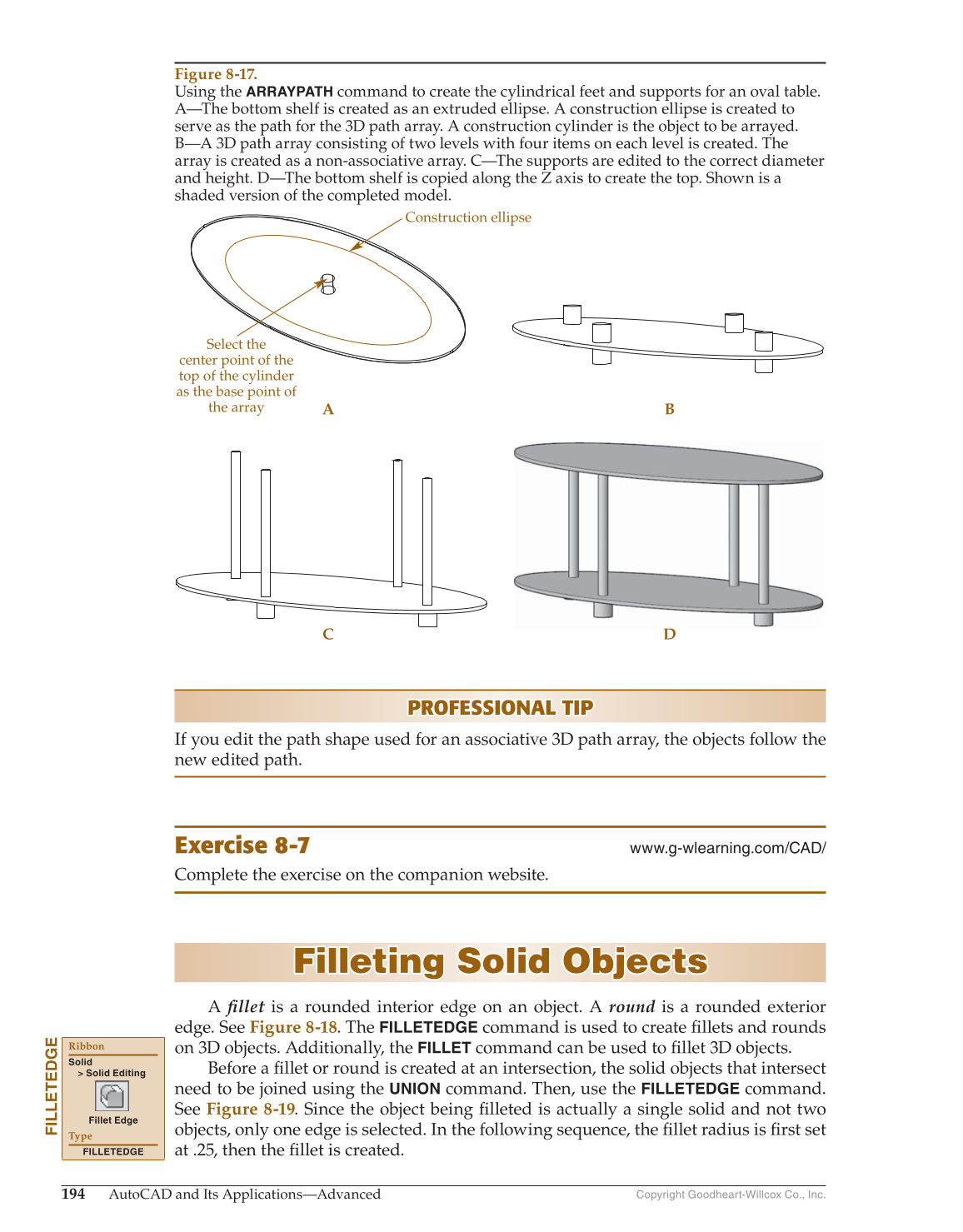
Figure 8-17.
Using the
ARRAYPATH
command to create the cylindrical feet and supports for an oval table.
A—The bottom shelf is created as an extruded ellipse. A construction ellipse is created to
serve as the path for the 3D path array. A construction cylinder is the object to be arrayed.
B—A 3D path array consisting of two levels with four items on each level is created. The
array is created as a non-associative array. C—The supports are edited to the correct diameter
and height. D—The bottom shelf is copied along the Z axis to create the top. Shown is a
shaded version of the completed model.