Copyright Goodheart-Willcox Co., Inc.
Chapter 8 Creating and Working with Solid Model Features
197
Once all edges are selected, press [Enter]. A preview with linear stretch grips appears
and you are prompted to accept the chamfer. If the current chamfer distances are
acceptable, press [Enter]. If not, enter the
Distance
option or use the linear stretch grips
to set new distance values.
The
CHAMFER
command works in a similar manner. After you enter the command,
you must select the edge you want to chamfer. When you make the selection, one of
the two surfaces corresponding to the edge is highlighted. The highlighted surface is
the base surface and is associated with the fi rst chamfer distance. If the highlighted
surface is not the one you want as the base surface, enter
N
at the
[Next/OK]
prompt
and press [Enter]. This highlights the next surface. An edge is created by two surfaces.
Therefore, when you enter
N
for the next surface, AutoCAD cycles through only two
surfaces. When the proper base surface is highlighted, press [Enter].
Using the
CHAMFER
command to chamfer a hole is shown in Figure 8-22A. In
Figure 8-22B, the cylinder is unioned to the base in order to create the chamfer at the
intersection. The ends of the cylinder in Figure 8-22B are chamfered by fi rst picking
a vertical isoline on the cylindrical face to defi ne the base surface. Then, the top edge
is selected, followed by the intersection edge. The following command sequence is
illustrated in Figure 8-22A.
(TRIM mode) Current chamfer Dist1 = 1.0000, Dist2 = 1.0000
Select first line or [Undo/Polyline/Distance/Angle/Trim/mEthod/Multiple]:
(select a
top edge)
Base surface selection...
Enter surface selection option [Next/OK (current)] OK:
(select
Next
if the top sur-
face is not selected or press [Enter])
Specify base surface chamfer distance or [Expression] 1.0000: .125↵
Specify other surface chamfer distance or [Expression] 1.0000: .125↵
Select an edge or [Loop]:
(select the hole diameter edge)
Select an edge or [Loop]: ↵
NOTE NOTE
Editing a fi llet or chamfer is discussed in Chapter 11. The
SOLIDEDIT
command
discussed in Chapter 12 can also be used to edit a fi llet or chamfer.
Exercise 8-8
www.g-wlearning.com/CAD/
Complete the exercise on the companion website.
CHAMFER
Ribbon
Home
Modify
Chamfer
Type
CHAMFER
CHA
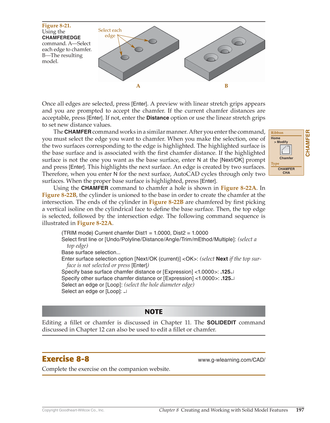
Select each
edge
A B
Figure 8-21.
Using the
CHAMFEREDGE
command. A—Select
each edge to chamfer.
B—The resulting
model.