Copyright Goodheart-Willcox Co., Inc.
Chapter 8 Creating and Working with Solid Model Features
201
Surface
A surface object can be used as the slicing path. The surface can be planar or
nonplanar (curved). Surface modeling is discussed in detail in Chapter 10. Using a
surface as a slicing path is a technique that you can use to quickly create a mating die.
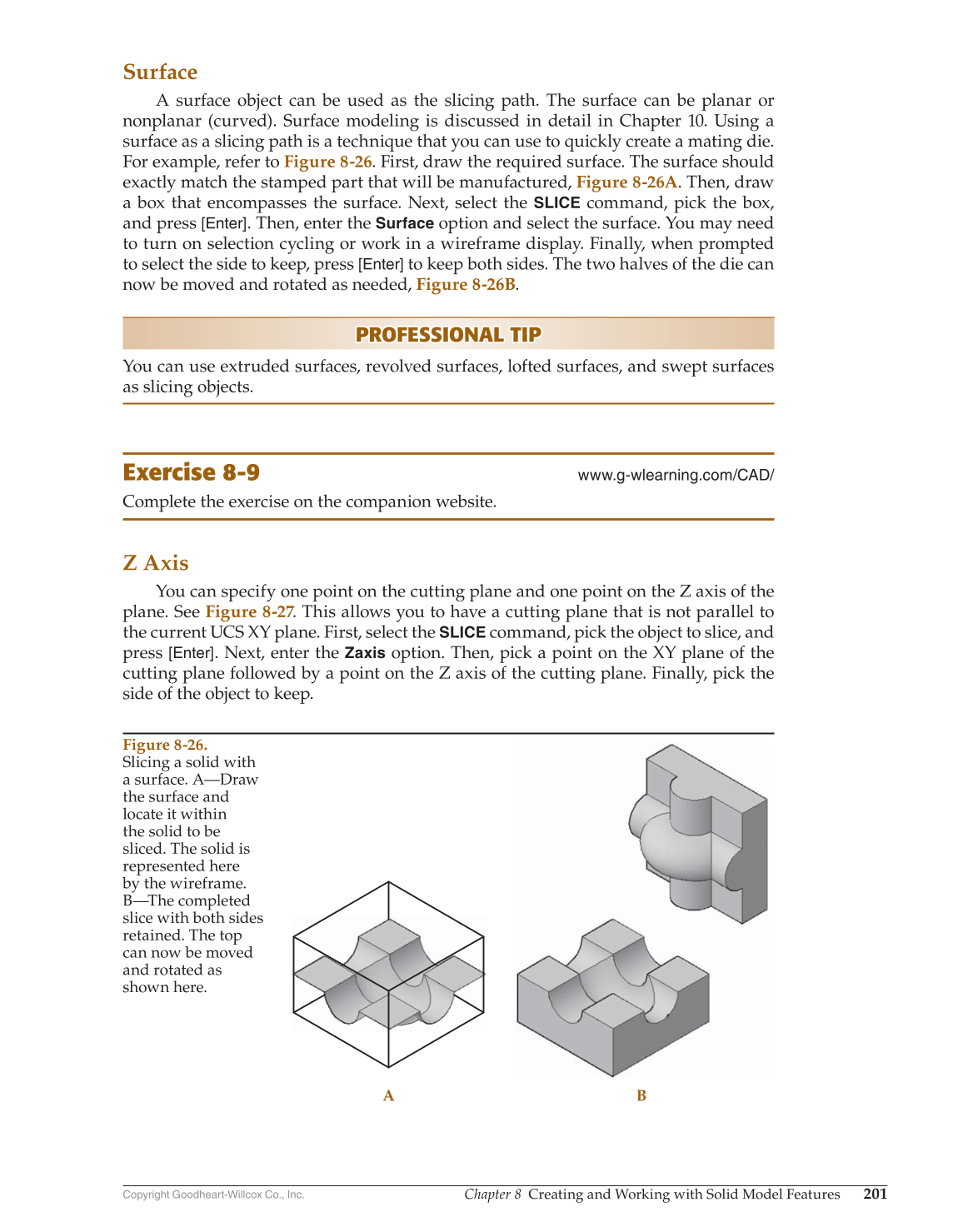
For example, refer to Figure 8-26. First, draw the required surface. The surface should
exactly match the stamped part that will be manufactured, Figure 8-26A. Then, draw
a box that encompasses the surface. Next, select the
SLICE
command, pick the box,
and press [Enter]. Then, enter the
Surface
option and select the surface. You may need
to turn on selection cycling or work in a wireframe display. Finally, when prompted
to select the side to keep, press
[Enter]
to keep both sides. The two halves of the die can
now be moved and rotated as needed, Figure 8-26B.
PROFESSIONAL TIP PROFESSIONAL TIP
You can use extruded surfaces, revolved surfaces, lofted surfaces, and swept surfaces
as slicing objects.
Exercise 8-9
www.g-wlearning.com/CAD/
Complete the exercise on the companion website.
Z Axis
You can specify one point on the cutting plane and one point on the Z axis of the
plane. See Figure 8-27. This allows you to have a cutting plane that is not parallel to
the current UCS XY plane. First, select the
SLICE
command, pick the object to slice, and
press [Enter]. Next, enter the
Zaxis
option. Then, pick a point on the XY plane of the
cutting plane followed by a point on the Z axis of the cutting plane. Finally, pick the
side of the object to keep.
A B
Figure 8-26.
Slicing a solid with
a surface. A—Draw
the surface and
locate it within
the solid to be
sliced. The solid is
represented here
by the wireframe.
B—The completed
slice with both sides
retained. The top
can now be moved
and rotated as
shown here.