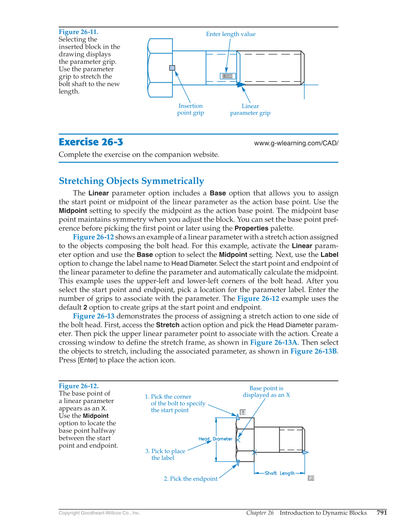
Chapter 26 Introduction to Dynamic Blocks 791 Copyright Goodheart-Willcox Co., Inc. Exercise 26-3 www.g-wlearning.com/CAD/ Complete the exercise on the companion website. Stretching Objects Symmetrically The Linear parameter option includes a Base option that allows you to assign the start point or midpoint of the linear parameter as the action base point. Use the Midpoint setting to specify the midpoint as the action base point. The midpoint base point maintains symmetry when you adjust the block. You can set the base point pref- erence before picking the fi rst point or later using the Properties palette. Figure 26-12 shows an example of a linear parameter with a stretch action assigned to the objects composing the bolt head. For this example, activate the Linear param- eter option and use the Base option to select the Midpoint setting. Next, use the Label option to change the label name to Head Diameter. Select the start point and endpoint of the linear parameter to defi ne the parameter and automatically calculate the midpoint. This example uses the upper-left and lower-left corners of the bolt head. After you select the start point and endpoint, pick a location for the parameter label. Enter the number of grips to associate with the parameter. The Figure 26-12 example uses the default 2 option to create grips at the start point and endpoint. Figure 26-13 demonstrates the process of assigning a stretch action to one side of the bolt head. First, access the Stretch action option and pick the Head Diameter param- eter. Then pick the upper linear parameter point to associate with the action. Create a crossing window to defi ne the stretch frame, as shown in Figure 26-13A. Then select the objects to stretch, including the associated parameter, as shown in Figure 26-13B. Press [Enter] to place the action icon. Figure 26-11. Selecting the inserted block in the drawing displays the parameter grip. Use the parameter grip to stretch the bolt shaft to the new length. Enter length value Insertion point grip Linear parameter grip Figure 26-12. The base point of a linear parameter appears as an X. Use the Midpoint option to locate the base point halfway between the start point and endpoint. Base point is displayed as an X 1. Pick the corner of the bolt to specify the start point 2. Pick the endpoint 3. Pick to place the label