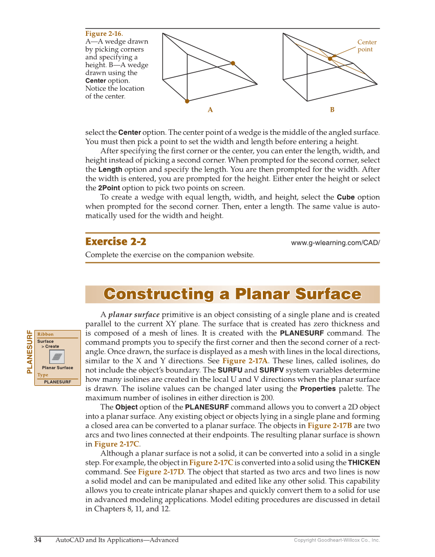
34 AutoCAD and Its Applications—Advanced Copyright Goodheart-Willcox Co., Inc. select the Center option. The center point of a wedge is the middle of the angled surface. You must then pick a point to set the width and length before entering a height. After specifying the fi rst corner or the center, you can enter the length, width, and height instead of picking a second corner. When prompted for the second corner, select the Length option and specify the length. You are then prompted for the width. After the width is entered, you are prompted for the height. Either enter the height or select the 2Point option to pick two points on screen. To create a wedge with equal length, width, and height, select the Cube option when prompted for the second corner. Then, enter a length. The same value is auto- matically used for the width and height. Exercise 2-2 www.g-wlearning.com/CAD/ Complete the exercise on the companion website. Constructing a Planar Surface Constructing a Planar Surface A planar surface primitive is an object consisting of a single plane and is created parallel to the current XY plane. The surface that is created has zero thickness and is composed of a mesh of lines. It is created with the PLANESURF command. The command prompts you to specify the fi rst corner and then the second corner of a rect- angle. Once drawn, the surface is displayed as a mesh with lines in the local directions, similar to the X and Y directions. See Figure 2-17A. These lines, called isolines, do not include the object’s boundary. The SURFU and SURFV system variables determine how many isolines are created in the local U and V directions when the planar surface is drawn. The isoline values can be changed later using the Properties palette. The maximum number of isolines in either direction is 200. The Object option of the PLANESURF command allows you to convert a 2D object into a planar surface. Any existing object or objects lying in a single plane and forming a closed area can be converted to a planar surface. The objects in Figure 2-17B are two arcs and two lines connected at their endpoints. The resulting planar surface is shown in Figure 2-17C. Although a planar surface is not a solid, it can be converted into a solid in a single step. For example, the object in Figure 2-17C is converted into a solid using the THICKEN command. See Figure 2-17D. The object that started as two arcs and two lines is now a solid model and can be manipulated and edited like any other solid. This capability allows you to create intricate planar shapes and quickly convert them to a solid for use in advanced modeling applications. Model editing procedures are discussed in detail in Chapters 8, 11, and 12. PLANESURF Ribbon Surface Create Planar Surface Type PLANESURF Center point A B Figure 2-16. A—A wedge drawn by picking corners and specifying a height. B—A wedge drawn using the Center option. Notice the location of the center.