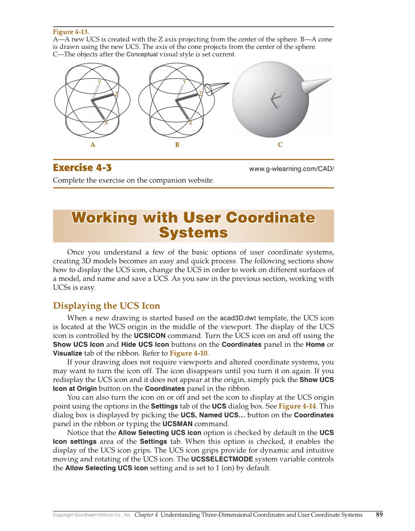
Copyright Goodheart-Willcox Co., Inc. Chapter 4 Understanding Three-Dimensional Coordinates and User Coordinate Systems 89 Exercise 4-3 www.g-wlearning.com/CAD/ Complete the exercise on the companion website. Working with User Coordinate Working with User Coordinate Systems Systems Once you understand a few of the basic options of user coordinate systems, creating 3D models becomes an easy and quick process. The following sections show how to display the UCS icon, change the UCS in order to work on different surfaces of a model, and name and save a UCS. As you saw in the previous section, working with UCSs is easy. Displaying the UCS Icon When a new drawing is started based on the acad3D.dwt template, the UCS icon is located at the WCS origin in the middle of the viewport. The display of the UCS icon is controlled by the UCSICON command. Turn the UCS icon on and off using the Show UCS Icon and Hide UCS Icon buttons on the Coordinates panel in the Home or Visualize tab of the ribbon. Refer to Figure 4-10. If your drawing does not require viewports and altered coordinate systems, you may want to turn the icon off. The icon disappears until you turn it on again. If you redisplay the UCS icon and it does not appear at the origin, simply pick the Show UCS Icon at Origin button on the Coordinates panel in the ribbon. You can also turn the icon on or off and set the icon to display at the UCS origin point using the options in the Settings tab of the UCS dialog box. See Figure 4-14. This dialog box is displayed by picking the UCS, Named UCS… button on the Coordinates panel in the ribbon or typing the UCSMAN command. Notice that the Allow Selecting UCS icon option is checked by default in the UCS Icon settings area of the Settings tab. When this option is checked, it enables the display of the UCS icon grips. The UCS icon grips provide for dynamic and intuitive moving and rotating of the UCS icon. The UCSSELECTMODE system variable controls the Allow Selecting UCS icon setting and is set to 1 (on) by default. A B C Figure 4-13. A—A new UCS is created with the Z axis projecting from the center of the sphere. B—A cone is drawn using the new UCS. The axis of the cone projects from the center of the sphere. C—The objects after the Conceptual visual style is set current.