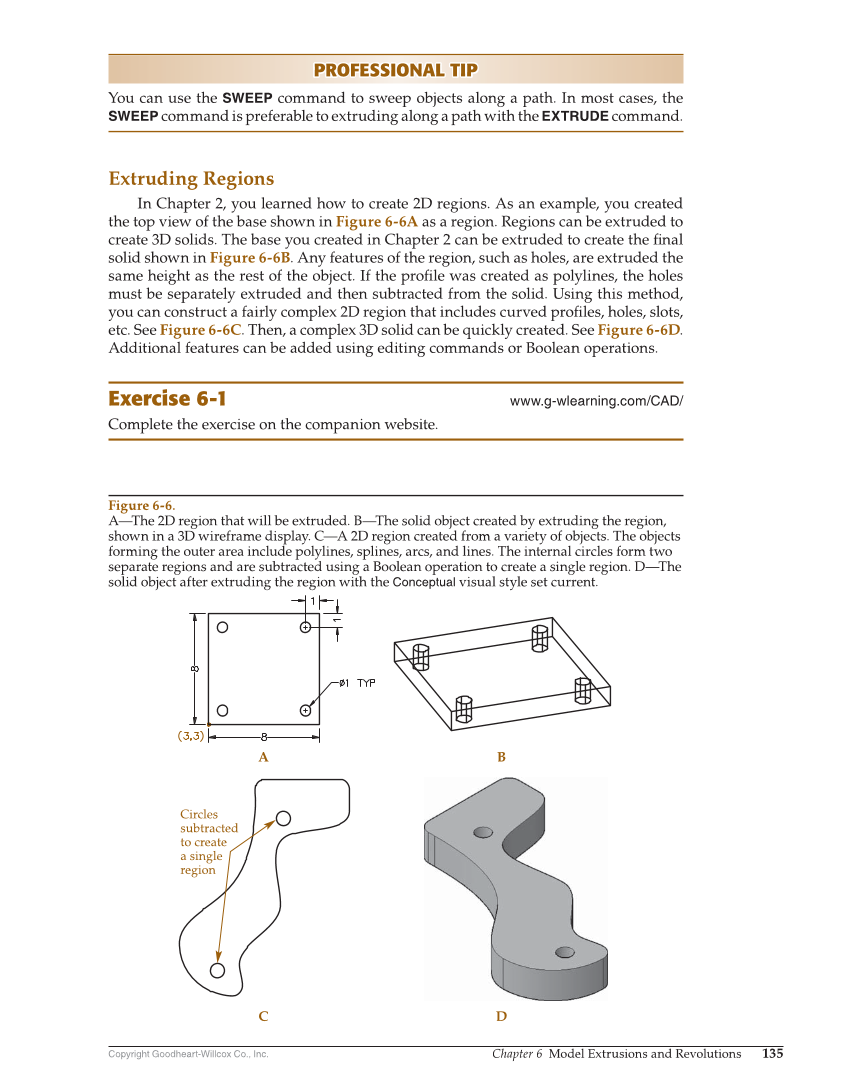
Copyright Goodheart-Willcox Co., Inc. Chapter 6 Model Extrusions and Revolutions 135 PROFESSIONAL TIP PROFESSIONAL TIP You can use the SWEEP command to sweep objects along a path. In most cases, the SWEEP command is preferable to extruding along a path with the EXTRUDE command. Extruding Regions In Chapter 2, you learned how to create 2D regions. As an example, you created the top view of the base shown in Figure 6-6A as a region. Regions can be extruded to create 3D solids. The base you created in Chapter 2 can be extruded to create the fi nal solid shown in Figure 6-6B. Any features of the region, such as holes, are extruded the same height as the rest of the object. If the profi le was created as polylines, the holes must be separately extruded and then subtracted from the solid. Using this method, you can construct a fairly complex 2D region that includes curved profi les, holes, slots, etc. See Figure 6-6C. Then, a complex 3D solid can be quickly created. See Figure 6-6D. Additional features can be added using editing commands or Boolean operations. Exercise 6-1 www.g-wlearning.com/CAD/ Complete the exercise on the companion website. C A B D Circles subtracted to create a single region Figure 6-6. A—The 2D region that will be extruded. B—The solid object created by extruding the region, shown in a 3D wireframe display. C—A 2D region created from a variety of objects. The objects forming the outer area include polylines, splines, arcs, and lines. The internal circles form two separate regions and are subtracted using a Boolean operation to create a single region. D—The solid object after extruding the region with the Conceptual visual style set current.