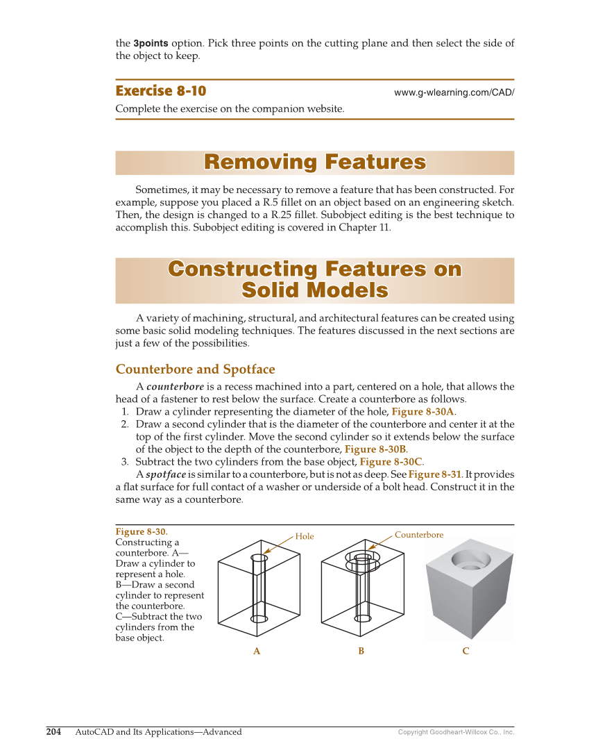
Copyright Goodheart-Willcox Co., Inc. 204 AutoCAD and Its Applications—Advanced Hole A B C Counterbore Figure 8-30. Constructing a counterbore. A— Draw a cylinder to represent a hole. B—Draw a second cylinder to represent the counterbore. C—Subtract the two cylinders from the base object. the 3points option. Pick three points on the cutting plane and then select the side of the object to keep. Exercise 8-10 www.g-wlearning.com/CAD/ Complete the exercise on the companion website. Removing Features Removing Features Sometimes, it may be necessary to remove a feature that has been constructed. For example, suppose you placed a R.5 fi llet on an object based on an engineering sketch. Then, the design is changed to a R.25 fi llet. Subobject editing is the best technique to accomplish this. Subobject editing is covered in Chapter 11. Constructing Features on Constructing Features on Solid Models Solid Models A variety of machining, structural, and architectural features can be created using some basic solid modeling techniques. The features discussed in the next sections are just a few of the possibilities. Counterbore and Spotface A counterbore is a recess machined into a part, centered on a hole, that allows the head of a fastener to rest below the surface. Create a counterbore as follows. 1. Draw a cylinder representing the diameter of the hole, Figure 8-30A. 2. Draw a second cylinder that is the diameter of the counterbore and center it at the top of the first cylinder. Move the second cylinder so it extends below the surface of the object to the depth of the counterbore, Figure 8-30B. 3. Subtract the two cylinders from the base object, Figure 8-30C. A spotface is similar to a counterbore, but is not as deep. See Figure 8-31. It provides a fl at surface for full contact of a washer or underside of a bolt head. Construct it in the same way as a counterbore.