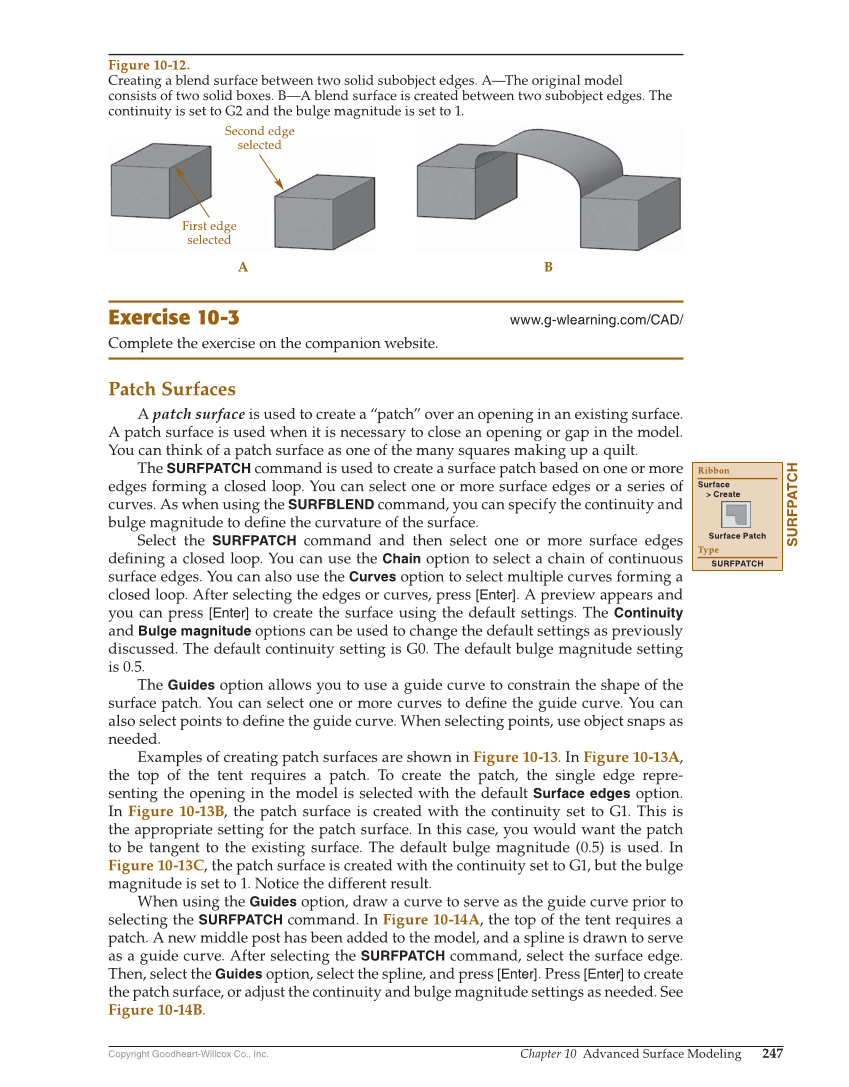
Copyright Goodheart-Willcox Co., Inc. Chapter 10 Advanced Surface Modeling 247 Exercise 10-3 www.g-wlearning.com/CAD/ Complete the exercise on the companion website. Patch Surfaces A patch surface is used to create a “patch” over an opening in an existing surface. A patch surface is used when it is necessary to close an opening or gap in the model. You can think of a patch surface as one of the many squares making up a quilt. The SURFPATCH command is used to create a surface patch based on one or more edges forming a closed loop. You can select one or more surface edges or a series of curves. As when using the SURFBLEND command, you can specify the continuity and bulge magnitude to defi ne the curvature of the surface. Select the SURFPATCH command and then select one or more surface edges defi ning a closed loop. You can use the Chain option to select a chain of continuous surface edges. You can also use the Curves option to select multiple curves forming a closed loop. After selecting the edges or curves, press [Enter]. A preview appears and you can press [Enter] to create the surface using the default settings. The Continuity and Bulge magnitude options can be used to change the default settings as previously discussed. The default continuity setting is G0. The default bulge magnitude setting is 0.5. The Guides option allows you to use a guide curve to constrain the shape of the surface patch. You can select one or more curves to defi ne the guide curve. You can also select points to defi ne the guide curve. When selecting points, use object snaps as needed. Examples of creating patch surfaces are shown in Figure 10-13. In Figure 10-13A, the top of the tent requires a patch. To create the patch, the single edge repre- senting the opening in the model is selected with the default Surface edges option. In Figure 10-13B, the patch surface is created with the continuity set to G1. This is the appropriate setting for the patch surface. In this case, you would want the patch to be tangent to the existing surface. The default bulge magnitude (0.5) is used. In Figure 10-13C, the patch surface is created with the continuity set to G1, but the bulge magnitude is set to 1. Notice the different result. When using the Guides option, draw a curve to serve as the guide curve prior to selecting the SURFPATCH command. In Figure 10-14A, the top of the tent requires a patch. A new middle post has been added to the model, and a spline is drawn to serve as a guide curve. After selecting the SURFPATCH command, select the surface edge. Then, select the Guides option, select the spline, and press [Enter]. Press [Enter] to create the patch surface, or adjust the continuity and bulge magnitude settings as needed. See Figure 10-14B. SURFPATCH Ribbon Surface Create Surface Patch Type SURFPATCH A B First edge selected Second edge selected Figure 10-12. Creating a blend surface between two solid subobject edges. A—The original model consists of two solid boxes. B—A blend surface is created between two subobject edges. The continuity is set to G2 and the bulge magnitude is set to 1.
