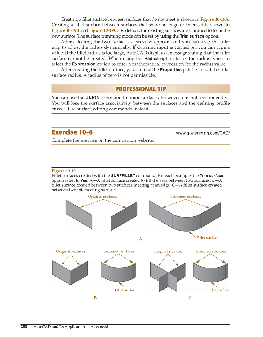
252 AutoCAD and Its Applications—Advanced 252 AutoCAD and Its Applications—Advanced Creating a fi llet surface between surfaces that do not meet is shown in Figure 10-19A. Creating a fi llet surface between surfaces that share an edge or intersect is shown in Figure 10-19B and Figure 10-19C. By default, the existing surfaces are trimmed to form the new surface. The surface trimming mode can be set by using the Trim surface option. After selecting the two surfaces, a preview appears and you can drag the fi llet grip to adjust the radius dynamically. If dynamic input is turned on, you can type a value. If the fi llet radius is too large, AutoCAD displays a message stating that the fi llet surface cannot be created. When using the Radius option to set the radius, you can select the Expression option to enter a mathematical expression for the radius value. After creating the fi llet surface, you can use the Properties palette to edit the fi llet surface radius. A radius of zero is not permissible. PROFESSIONAL TIP PROFESSIONAL TIP You can use the UNION command to union surfaces. However, it is not recommended. You will lose the surface associativity between the surfaces and the defi ning profi le curves. Use surface editing commands instead. Exercise 10-6 www.g-wlearning.com/CAD/ Complete the exercise on the companion website. A B C Fillet surface Original surfaces Trimmed surfaces Original surfaces Trimmed surfaces Original surfaces Trimmed surfaces Fillet surface Fillet surface Figure 10-19. Fillet surfaces created with the SURFFILLET command. For each example, the Trim surface option is set to Yes. A—A fillet surface created to fill the area between two surfaces. B—A fillet surface created between two surfaces meeting at an edge. C—A fillet surface created between two intersecting surfaces.