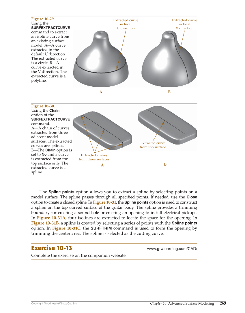
Copyright Goodheart-Willcox Co., Inc. Chapter 10 Advanced Surface Modeling 263 The Spline points option allows you to extract a spline by selecting points on a model surface. The spline passes through all specifi ed points. If needed, use the Close option to create a closed spline. In Figure 10-31, the Spline points option is used to construct a spline on the top curved surface of the guitar body. The spline provides a trimming boundary for creating a sound hole or creating an opening to install electrical pickups. In Figure 10-31A, four isolines are extracted to locate the space for the opening. In Figure 10-31B, a spline is created by selecting a series of points with the Spline points option. In Figure 10-31C, the SURFTRIM command is used to form the opening by trimming the center area. The spline is selected as the cutting curve. Exercise 10-13 www.g-wlearning.com/CAD/ Complete the exercise on the companion website. Extracted curve in local U direction Extracted curve in local V direction A B Figure 10-29. Using the SURFEXTRACTCURVE command to extract an isoline curve from an existing surface model. A—A curve extracted in the default U direction. The extracted curve is a circle. B—A curve extracted in the V direction. The extracted curve is a polyline. Extracted curve from top surface A B Extracted curves from three surfaces Figure 10-30. Using the Chain option of the SURFEXTRACTCURVE command. A—A chain of curves extracted from three adjacent model surfaces. The extracted curves are splines. B—The Chain option is set to No and a curve is extracted from the top surface only. The extracted curve is a spline.