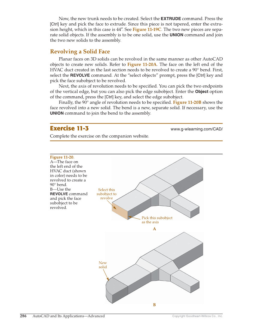
Copyright Goodheart-Willcox Co., Inc. 286 AutoCAD and Its Applications—Advanced Now, the new trunk needs to be created. Select the EXTRUDE command. Press the [Ctrl] key and pick the face to extrude. Since this piece is not tapered, enter the extru- sion height, which in this case is 44″. See Figure 11-19C. The two new pieces are sepa- rate solid objects. If the assembly is to be one solid, use the UNION command and join the two new solids to the assembly. Revolving a Solid Face Planar faces on 3D solids can be revolved in the same manner as other AutoCAD objects to create new solids. Refer to Figure 11-20A. The face on the left end of the HVAC duct created in the last section needs to be revolved to create a 90° bend. First, select the REVOLVE command. At the “select objects” prompt, press the [Ctrl] key and pick the face subobject to be revolved. Next, the axis of revolution needs to be specifi ed. You can pick the two endpoints of the vertical edge, but you can also pick the edge subobject. Enter the Object option of the command, press the [Ctrl] key, and select the edge subobject. Finally, the 90° angle of revolution needs to be specifi ed. Figure 11-20B shows the face revolved into a new solid. The bend is a new, separate solid. If necessary, use the UNION command to join the bend to the assembly. Exercise 11-3 www.g-wlearning.com/CAD/ Complete the exercise on the companion website. Select this subobject to revolve A Pick this subobject as the axis New solid B Figure 11-20. A—The face on the left end of the HVAC duct (shown in color) needs to be revolved to create a 90° bend. B—Use the REVOLVE command and pick the face subobject to be revolved.