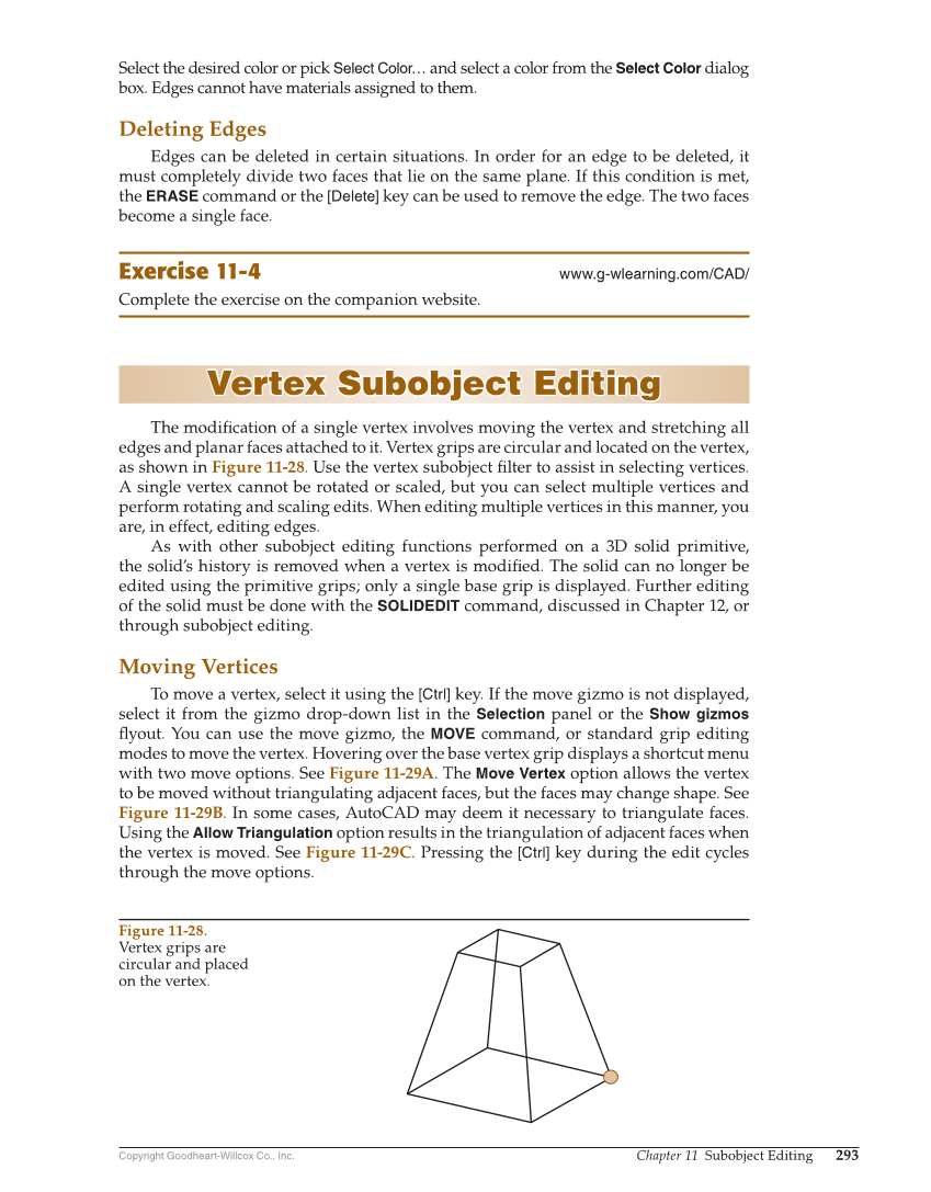
Copyright Goodheart-Willcox Co., Inc. Chapter 11 Subobject Editing 293 Select the desired color or pick Select Color… and select a color from the Select Color dialog box. Edges cannot have materials assigned to them. Deleting Edges Edges can be deleted in certain situations. In order for an edge to be deleted, it must completely divide two faces that lie on the same plane. If this condition is met, the ERASE command or the [Delete] key can be used to remove the edge. The two faces become a single face. Exercise 11-4 www.g-wlearning.com/CAD/ Complete the exercise on the companion website. Vertex Subobject Editing Vertex Subobject Editing The modifi cation of a single vertex involves moving the vertex and stretching all edges and planar faces attached to it. Vertex grips are circular and located on the vertex, as shown in Figure 11-28. Use the vertex subobject fi lter to assist in selecting vertices. A single vertex cannot be rotated or scaled, but you can select multiple vertices and perform rotating and scaling edits. When editing multiple vertices in this manner, you are, in effect, editing edges. As with other subobject editing functions performed on a 3D solid primitive, the solid’s history is removed when a vertex is modifi ed. The solid can no longer be edited using the primitive grips only a single base grip is displayed. Further editing of the solid must be done with the SOLIDEDIT command, discussed in Chapter 12, or through subobject editing. Moving Vertices To move a vertex, select it using the [Ctrl] key. If the move gizmo is not displayed, select it from the gizmo drop-down list in the Selection panel or the Show gizmos fl yout. You can use the move gizmo, the MOVE command, or standard grip editing modes to move the vertex. Hovering over the base vertex grip displays a shortcut menu with two move options. See Figure 11-29A. The Move Vertex option allows the vertex to be moved without triangulating adjacent faces, but the faces may change shape. See Figure 11-29B. In some cases, AutoCAD may deem it necessary to triangulate faces. Using the Allow Triangulation option results in the triangulation of adjacent faces when the vertex is moved. See Figure 11-29C. Pressing the [Ctrl] key during the edit cycles through the move options. Figure 11-28. Vertex grips are circular and placed on the vertex.