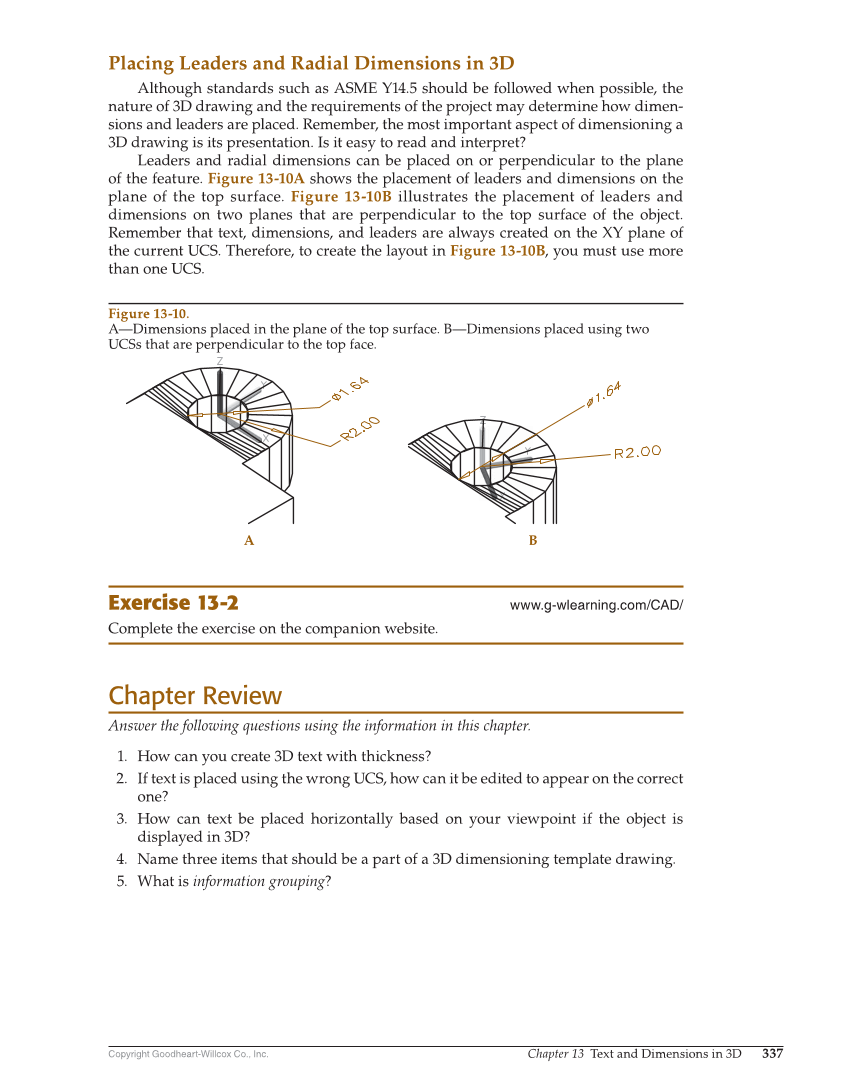
Copyright Goodheart-Willcox Co., Inc. Chapter 13 Text and Dimensions in 3D 337 Placing Leaders and Radial Dimensions in 3D Although standards such as ASME Y14.5 should be followed when possible, the nature of 3D drawing and the requirements of the project may determine how dimen- sions and leaders are placed. Remember, the most important aspect of dimensioning a 3D drawing is its presentation. Is it easy to read and interpret? Leaders and radial dimensions can be placed on or perpendicular to the plane of the feature. Figure 13-10A shows the placement of leaders and dimensions on the plane of the top surface. Figure 13-10B illustrates the placement of leaders and dimensions on two planes that are perpendicular to the top surface of the object. Remember that text, dimensions, and leaders are always created on the XY plane of the current UCS. Therefore, to create the layout in Figure 13-10B, you must use more than one UCS. Exercise 13-2 www.g-wlearning.com/CAD/ Complete the exercise on the companion website. Chapter Review Answer the following questions using the information in this chapter. 1. How can you create 3D text with thickness? 2. If text is placed using the wrong UCS, how can it be edited to appear on the correct one? 3. How can text be placed horizontally based on your viewpoint if the object is displayed in 3D? 4. Name three items that should be a part of a 3D dimensioning template drawing. 5. What is information grouping? A B Figure 13-10. A—Dimensions placed in the plane of the top surface. B—Dimensions placed using two UCSs that are perpendicular to the top face.