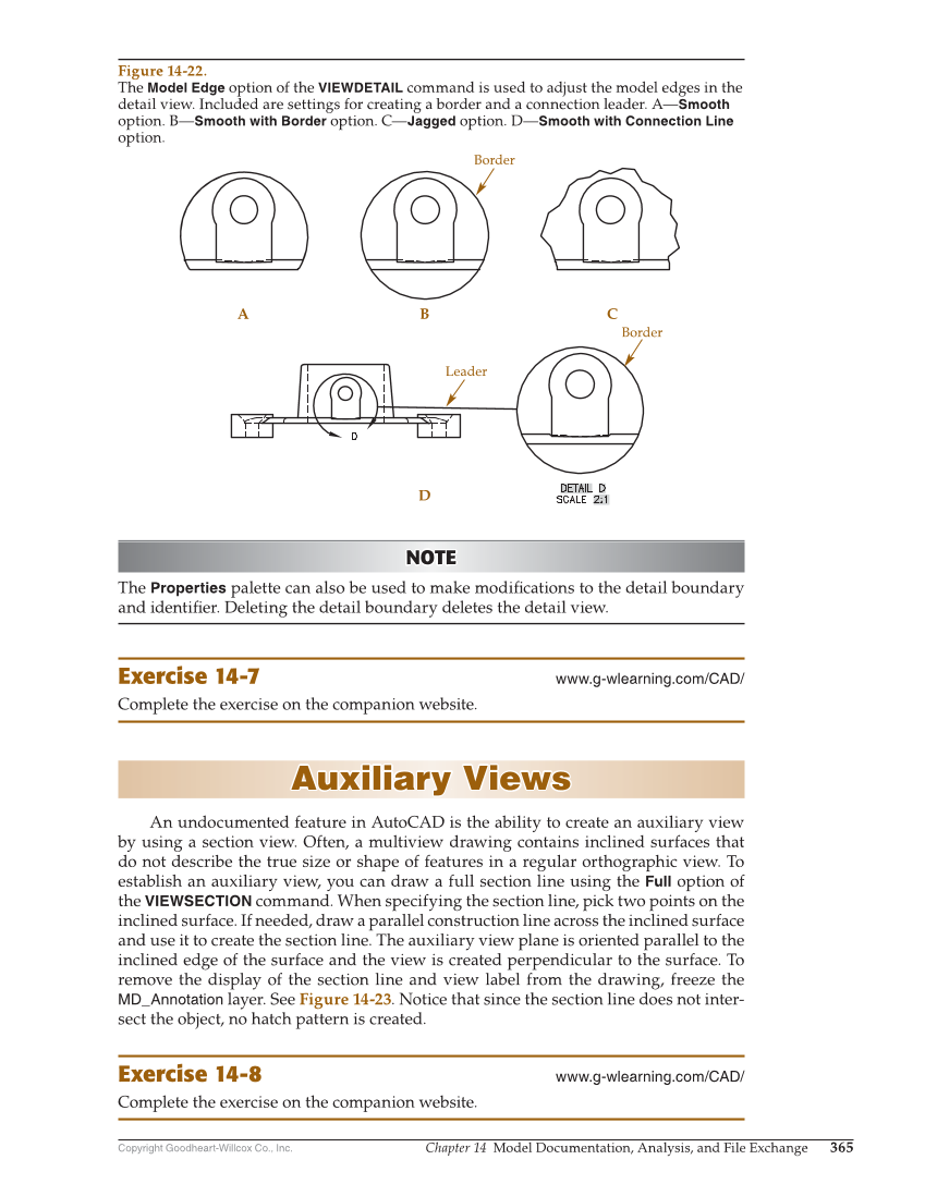
Copyright Goodheart-Willcox Co., Inc. Chapter 14 Model Documentation, Analysis, and File Exchange 365 NOTE NOTE The Properties palette can also be used to make modifi cations to the detail boundary and identifi er. Deleting the detail boundary deletes the detail view. Exercise 14-7 www.g-wlearning.com/CAD/ Complete the exercise on the companion website. Auxiliary Views Auxiliary Views An undocumented feature in AutoCAD is the ability to create an auxiliary view by using a section view. Often, a multiview drawing contains inclined surfaces that do not describe the true size or shape of features in a regular orthographic view. To establish an auxiliary view, you can draw a full section line using the Full option of the VIEWSECTION command. When specifying the section line, pick two points on the inclined surface. If needed, draw a parallel construction line across the inclined surface and use it to create the section line. The auxiliary view plane is oriented parallel to the inclined edge of the surface and the view is created perpendicular to the surface. To remove the display of the section line and view label from the drawing, freeze the MD_Annotation layer. See Figure 14-23. Notice that since the section line does not inter- sect the object, no hatch pattern is created. Exercise 14-8 www.g-wlearning.com/CAD/ Complete the exercise on the companion website. Border A B D C Border Leader Figure 14-22. The Model Edge option of the VIEWDETAIL command is used to adjust the model edges in the detail view. Included are settings for creating a border and a connection leader. A—Smooth option. B—Smooth with Border option. C—Jagged option. D—Smooth with Connection Line option.