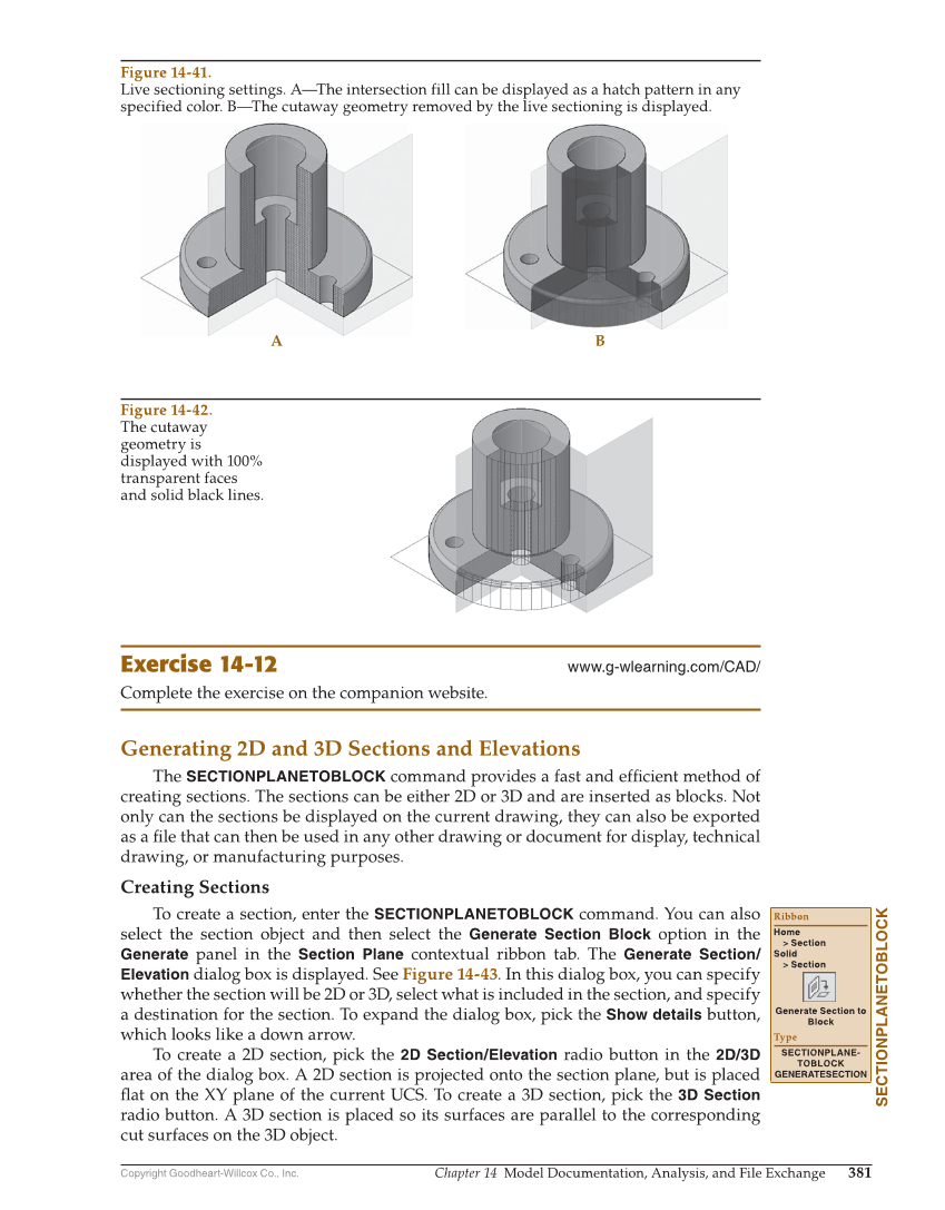
Copyright Goodheart-Willcox Co., Inc. Chapter 14 Model Documentation, Analysis, and File Exchange 381 Exercise 14-12 www.g-wlearning.com/CAD/ Complete the exercise on the companion website. Generating 2D and 3D Sections and Elevations The SECTIONPLANETOBLOCK command provides a fast and effi cient method of creating sections. The sections can be either 2D or 3D and are inserted as blocks. Not only can the sections be displayed on the current drawing, they can also be exported as a fi le that can then be used in any other drawing or document for display, technical drawing, or manufacturing purposes. Creating Sections To create a section, enter the SECTIONPLANETOBLOCK command. You can also select the section object and then select the Generate Section Block option in the Generate panel in the Section Plane contextual ribbon tab. The Generate Section/ Elevation dialog box is displayed. See Figure 14-43. In this dialog box, you can specify whether the section will be 2D or 3D, select what is included in the section, and specify a destination for the section. To expand the dialog box, pick the Show details button, which looks like a down arrow. To create a 2D section, pick the 2D Section/Elevation radio button in the 2D/3D area of the dialog box. A 2D section is projected onto the section plane, but is placed fl at on the XY plane of the current UCS. To create a 3D section, pick the 3D Section radio button. A 3D section is placed so its surfaces are parallel to the corresponding cut surfaces on the 3D object. SECTIONPLANETOBLOCK Ribbon Home Section Solid Section Generate Section to Block Type SECTIONPLANE- TOBLOCK GENERATESECTION A B Figure 14-41. Live sectioning settings. A—The intersection fill can be displayed as a hatch pattern in any specified color. B—The cutaway geometry removed by the live sectioning is displayed. Figure 14-42. The cutaway geometry is displayed with 100% transparent faces and solid black lines.
