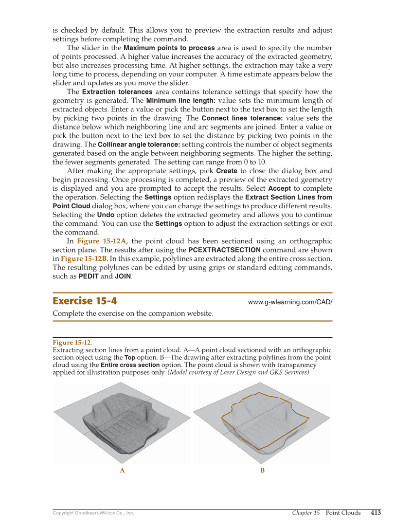
Copyright Goodheart-Willcox Co., Inc. Chapter 15 Point Clouds 413 is checked by default. This allows you to preview the extraction results and adjust settings before completing the command. The slider in the Maximum points to process area is used to specify the number of points processed. A higher value increases the accuracy of the extracted geometry, but also increases processing time. At higher settings, the extraction may take a very long time to process, depending on your computer. A time estimate appears below the slider and updates as you move the slider. The Extraction tolerances area contains tolerance settings that specify how the geometry is generated. The Minimum line length: value sets the minimum length of extracted objects. Enter a value or pick the button next to the text box to set the length by picking two points in the drawing. The Connect lines tolerance: value sets the distance below which neighboring line and arc segments are joined. Enter a value or pick the button next to the text box to set the distance by picking two points in the drawing. The Collinear angle tolerance: setting controls the number of object segments generated based on the angle between neighboring segments. The higher the setting, the fewer segments generated. The setting can range from 0 to 10. After making the appropriate settings, pick Create to close the dialog box and begin processing. Once processing is completed, a preview of the extracted geometry is displayed and you are prompted to accept the results. Select Accept to complete the operation. Selecting the Settings option redisplays the Extract Section Lines from Point Cloud dialog box, where you can change the settings to produce different results. Selecting the Undo option deletes the extracted geometry and allows you to continue the command. You can use the Settings option to adjust the extraction settings or exit the command. In Figure 15-12A, the point cloud has been sectioned using an orthographic section plane. The results after using the PCEXTRACTSECTION command are shown in Figure 15-12B. In this example, polylines are extracted along the entire cross section. The resulting polylines can be edited by using grips or standard editing commands, such as PEDIT and JOIN. Exercise 15-4 www.g-wlearning.com/CAD/ Complete the exercise on the companion website. A B Figure 15-12. Extracting section lines from a point cloud. A—A point cloud sectioned with an orthographic section object using the Top option. B—The drawing after extracting polylines from the point cloud using the Entire cross section option. The point cloud is shown with transparency applied for illustration purposes only. (Model courtesy of Laser Design and GKS Services)