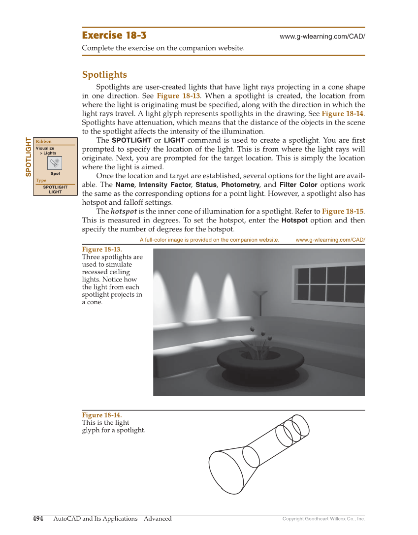
Copyright Goodheart-Willcox Co., Inc. 494 AutoCAD and Its Applications—Advanced Exercise 18-3 www.g-wlearning.com/CAD/ Complete the exercise on the companion website. Spotlights Spotlights are user-created lights that have light rays projecting in a cone shape in one direction. See Figure 18-13. When a spotlight is created, the location from where the light is originating must be specifi ed, along with the direction in which the light rays travel. A light glyph represents spotlights in the drawing. See Figure 18-14. Spotlights have attenuation, which means that the distance of the objects in the scene to the spotlight affects the intensity of the illumination. The SPOTLIGHT or LIGHT command is used to create a spotlight. You are fi rst prompted to specify the location of the light. This is from where the light rays will originate. Next, you are prompted for the target location. This is simply the location where the light is aimed. Once the location and target are established, several options for the light are avail- able. The Name, Intensity Factor, Status, Photometry, and Filter Color options work the same as the corresponding options for a point light. However, a spotlight also has hotspot and falloff settings. The hotspot is the inner cone of illumination for a spotlight. Refer to Figure 18-15. This is measured in degrees. To set the hotspot, enter the Hotspot option and then specify the number of degrees for the hotspot. SPOTLIGHT Ribbon Visualize Lights Spot Type SPOTLIGHT LIGHT Figure 18-13. Three spotlights are used to simulate recessed ceiling lights. Notice how the light from each spotlight projects in a cone. A full-color image is provided on the companion website. www.g-wlearning.com/CAD/ Figure 18-14. This is the light glyph for a spotlight.