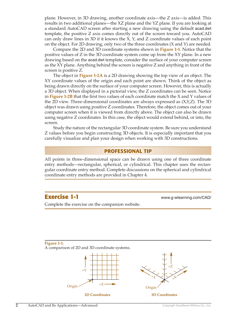
2 AutoCAD and Its Applications—Advanced Copyright Goodheart-Willcox Co., Inc. plane. However, in 3D drawing, another coordinate axis—the Z axis—is added. This results in two additional planes—the XZ plane and the YZ plane. If you are looking at a standard AutoCAD screen after starting a new drawing using the default acad.dwt template, the positive Z axis comes directly out of the screen toward you. AutoCAD can only draw lines in 3D if it knows the X, Y, and Z coordinate values of each point on the object. For 2D drawing, only two of the three coordinates (X and Y) are needed. Compare the 2D and 3D coordinate systems shown in Figure 1-1. Notice that the positive values of Z in the 3D coordinate system come up from the XY plane. In a new drawing based on the acad.dwt template, consider the surface of your computer screen as the XY plane. Anything behind the screen is negative Z and anything in front of the screen is positive Z. The object in Figure 1-2A is a 2D drawing showing the top view of an object. The XY coordinate values of the origin and each point are shown. Think of the object as being drawn directly on the surface of your computer screen. However, this is actually a 3D object. When displayed in a pictorial view, the Z coordinates can be seen. Notice in Figure 1-2B that the fi rst two values of each coordinate match the X and Y values of the 2D view. Three-dimensional coordinates are always expressed as (X,Y,Z). The 3D object was drawn using positive Z coordinates. Therefore, the object comes out of your computer screen when it is viewed from directly above. The object can also be drawn using negative Z coordinates. In this case, the object would extend behind, or into, the screen. Study the nature of the rectangular 3D coordinate system. Be sure you understand Z values before you begin constructing 3D objects. It is especially important that you carefully visualize and plan your design when working with 3D constructions. PROFESSIONAL TIP PROFESSIONAL TIP All points in three-dimensional space can be drawn using one of three coordinate entry methods—rectangular, spherical, or cylindrical. This chapter uses the rectan- gular coordinate entry method. Complete discussions on the spherical and cylindrical coordinate entry methods are provided in Chapter 4. Exercise 1-1 www.g-wlearning.com/CAD/ Complete the exercise on the companion website. Figure 1-1. A comparison of 2D and 3D coordinate systems. Origin 2D Coordinates 3D Coordinates Origin +Y +Y +Z +X +X