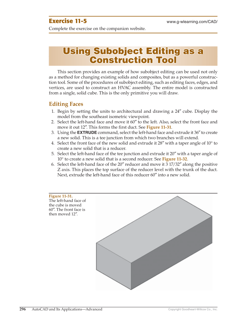
Copyright Goodheart-Willcox Co., Inc. 296 AutoCAD and Its Applications—Advanced Exercise 11-5 www.g-wlearning.com/CAD/ Complete the exercise on the companion website. Using Subobject Editing as a Using Subobject Editing as a Construction Tool Construction Tool This section provides an example of how subobject editing can be used not only as a method for changing existing solids and composites, but as a powerful construc- tion tool. Some of the procedures of subobject editing, such as editing faces, edges, and vertices, are used to construct an HVAC assembly. The entire model is constructed from a single, solid cube. This is the only primitive you will draw. Editing Faces 1. Begin by setting the units to architectural and drawing a 24″ cube. Display the model from the southeast isometric viewpoint. 2. Select the left-hand face and move it 60″ to the left. Also, select the front face and move it out 12″. This forms the first duct. See Figure 11-31. 3. Using the EXTRUDE command, select the left-hand face and extrude it 36″ to create a new solid. This is a tee junction from which two branches will extend. 4. Select the front face of the new solid and extrude it 28″ with a taper angle of 10° to create a new solid that is a reducer. 5. Select the left-hand face of the tee junction and extrude it 20″ with a taper angle of 10° to create a new solid that is a second reducer. See Figure 11-32. 6. Select the left-hand face of the 20″ reducer and move it 3 17/32″ along the positive Z axis. This places the top surface of the reducer level with the trunk of the duct. Next, extrude the left-hand face of this reducer 60″ into a new solid. Figure 11-31. The left-hand face of the cube is moved 60″. The front face is then moved 12″.