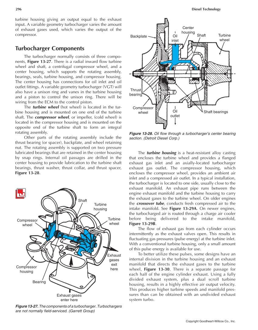
296 Diesel Technology Copyright Goodheart-Willcox Co., Inc. turbine housing giving an output equal to the exhaust input. A variable geometry turbocharger varies the amount of exhaust gases used, which varies the output of the compressor. Turbocharger Components The turbocharger normally consists of three compo- nents, Figure 13-27. There is a radial inward flow turbine wheel and shaft, a centrifugal compressor wheel, and a center housing, which supports the rotating assembly, bearings, seals, turbine housing, and compressor housing. The center housing has connections for oil inlet and oil outlet fittings. A variable geometry turbocharger (VGT) will also have a unison ring and vanes in the turbine housing and a piston to control the unison ring. There will be wiring from the ECM to the control piston. The turbine wheel (hot wheel) is located in the tur- bine housing and is mounted on one end of the turbine shaft. The compressor wheel, or impeller, (cold wheel) is located in the compressor housing and is mounted on the opposite end of the turbine shaft to form an integral rotating assembly. Other parts of the rotating assembly include the thrust bearing (or spacer), backplate, and wheel retaining nut. The rotating assembly is supported on two pressure lubricated bearings that are retained in the center housing by snap rings. Internal oil passages are drilled in the center housing to provide lubrication to the turbine shaft bearings, thrust washer, thrust collar, and thrust spacer, Figure 13-28. The turbine housing is a heat-resistant alloy casting that encloses the turbine wheel and provides a flanged exhaust gas inlet and an axially-located turbocharger exhaust gas outlet. The compressor housing, which encloses the compressor wheel, provides an ambient air inlet and a compressed air outlet. In a typical installation, the turbocharger is located to one side, usually close to the exhaust manifold. An exhaust pipe runs between the engine exhaust manifold and the turbine housing to carry the exhaust gases to the turbine wheel. On older engines the crossover tube, conducts fresh compressed air to the intake manifold. See Figure 13-29A. On newer engines, the turbocharged air is routed through a charge air cooler before being delivered to the intake manifold, Figure 13-29B. The flow of exhaust gas from each cylinder occurs intermittently as the exhaust valves open. This results in fluctuating gas pressures (pulse energy) at the turbine inlet. With a conventional turbine housing, only a small amount of this pulse energy is available for use. To better utilize these pulses, some designs have an internal division in the turbine housing and an exhaust manifold that directs the exhaust gases to the turbine wheel, Figure 13-30. There is a separate passage for each half of the engine cylinder exhaust. Using a fully divided exhaust system, plus a dual scroll turbine housing, results in a highly effective air output velocity. This produces higher turbine speeds and manifold pres- sures than can be obtained with an undivided exhaust system turbo. Shaft Turbine housing Turbine wheel Exhaust gases exit here Exhaust gases enter here Bearing Compressor housing Compressor wheel Figure 13-27. The components of a turbocharger. Turbochargers are not normally field-serviced. (Garrett Group) Backplate Oil inlet Oil outlet Compressor wheel Thrust bearing Center housing Shaft Turbine wheel Shaft bearings Figure 13-28. Oil flow through a turbocharger’s center bearing section. (Detroit Diesel Corp.)