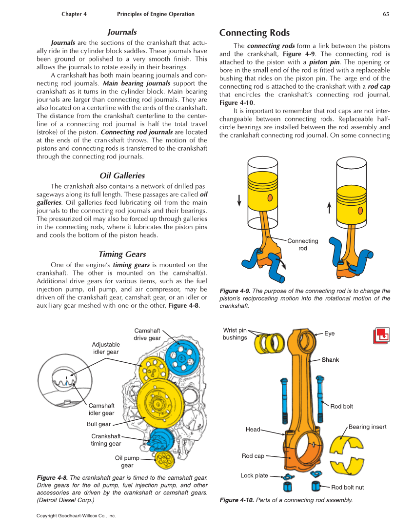
Chapter 4 Principles of Engine Operation 65 Copyright Goodheart-Willcox Co., Inc. Journals Journals are the sections of the crankshaft that actu- ally ride in the cylinder block saddles. These journals have been ground or polished to a very smooth finish. This allows the journals to rotate easily in their bearings. A crankshaft has both main bearing journals and con- necting rod journals. Main bearing journals support the crankshaft as it turns in the cylinder block. Main bearing journals are larger than connecting rod journals. They are also located on a centerline with the ends of the crankshaft. The distance from the crankshaft centerline to the center- line of a connecting rod journal is half the total travel (stroke) of the piston. Connecting rod journals are located at the ends of the crankshaft throws. The motion of the pistons and connecting rods is transferred to the crankshaft through the connecting rod journals. Oil Galleries The crankshaft also contains a network of drilled pas- s ageways along its full length. These passages are called oil galleries. Oil galleries feed lubricating oil from the main journals to the connecting rod journals and their bearings. The pressurized oil may also be forced up through galleries in the connecting rods, where it lubricates the piston pins and cools the bottom of the piston heads. Timing Gears One of the engine’s timing gears is mounted on the crankshaft. The other is mounted on the camshaft(s). Additional drive gears for various items, such as the fuel injection pump, oil pump, and air compressor, may be driven off the crankshaft gear, camshaft gear, or an idler or auxiliary gear meshed with one or the other, Figure 4-8. Connecting Rods The connecting rods form a link between the pistons and the crankshaft, Figure 4-9. The connecting rod is attached to the piston with a piston pin. The opening or bore in the small end of the rod is fitted with a replaceable bushing that rides on the piston pin. The large end of the connecting rod is attached to the crankshaft with a rod cap that encircles the crankshaft’s connecting rod journal, Figure 4-10. It is important to remember that rod caps are not inter- changeable between connecting rods. Replaceable half- circle bearings are installed between the rod assembly and the crankshaft connecting rod journal. On some connecting Camshaft drive gear Adjustable idler gear Camshaft idler gear Bull gear Crankshaft timing gear Oil pump gear Figure 4-8. The crankshaft gear is timed to the camshaft gear. Drive gears for the oil pump, fuel injection pump, and other accessories are driven by the crankshaft or camshaft gears. (Detroit Diesel Corp.) Connecting rod Figure 4-9. The purpose of the connecting rod is to change the piston’s reciprocating motion into the rotational motion of the crankshaft. Shank Eye Shank Wrist pin bushings Head Rod cap Lock plate Rod bolt Bearing insert Rod bolt nut Figure 4-10. Parts of a connecting rod assembly.