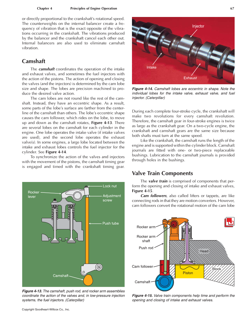
Chapter 4 Principles of Engine Operation 67 Copyright Goodheart-Willcox Co., Inc. or directly proportional to the crankshaft’s rotational speed. The counterweights on the internal balancer create a fre- quency of vibration that is the exact opposite of the vibra- tions occurring in the crankshaft. The vibrations produced by the balancer and the crankshaft cancel each other out. Internal balancers are also used to eliminate camshaft vibration. Camshaft The camshaft coordinates the operation of the intake and exhaust valves, and sometimes the fuel injectors with the action of the pistons. The action of opening and closing the valves (and the injectors) is determined by the cam lobe size and shape. The lobes are precision machined to pro- duce the desired valve action. The cam lobes are not round like the rest of the cam- shaft. Instead, they have an eccentric shape. As a result, some parts of the lobe’s surface are farther from the center- line of the camshaft than others. The lobe’s eccentric shape causes the cam follower, which rides on the lobe, to move up and down as the camshaft rotates, Figure 4-13. There are several lobes on the camshaft for each cylinder in the engine. One lobe operates the intake valve (if intake valves are used), and the second lobe operates the exhaust valve(s). In some engines, a large lobe located between the intake and exhaust lobes controls the fuel injector for the cylinder. See Figure 4-14. To synchronize the action of the valves and injectors with the movement of the pistons, the camshaft timing gear is engaged and timed with the crankshaft timing gear. During each complete four-stroke cycle, the crankshaft will make two revolutions for every camshaft revolution. Therefore, the camshaft gear in four-stroke engines is twice as large as the crankshaft gear. On a two-cycle engine, the crankshaft and camshaft gears are the same size because both shafts must turn at the same speed. Like the crankshaft, the camshaft runs the length of the engine and is supported within the cylinder block. Camshaft journals are fitted with one- or two-piece replaceable bushings. Lubrication to the camshaft journals is provided through holes in the bushings. Valve Train Components The valve train is comprised of components that per- form the opening and closing of intake and exhaust valves, Figure 4-15. Cam followers, also called lifters or tappets, are like connecting rods in that they are motion converters. However, cam followers convert the rotational motion of the cam lobe Lock nut Adjustment screw Push tube Rocker lever Camshaft Figure 4-13. The camshaft, push rod, and rocker arm assemblies coordinate the action of the valves and, in low-pressure injection systems, the fuel injectors. (Caterpillar) Injector Exhaust Intake Figure 4-14. Camshaft lobes are eccentric in shape. Note the individual lobes for the intake valve, exhaust valve, and fuel injector. (Caterpillar) Rocker arm Rocker arm shaft Push rod Cam follower Camshaft Head Piston Block Figure 4-15. Valve train components help time and perform the opening and closing of intake and exhaust valves.