156 Engineering Fundamentals
Solderless Breadboards
Solderless breadboards are ideal for experi-
mentation and testing circuits before they are
constructed. Components and leads can easily
be moved from one place to another because no
soldering is required to make connections. See
Figure 8-28.
Electronic Circuit Simulation
Engineers and technicians can now simulate
the performance of circuitry using computer soft-
ware without ever having to build an actual circuit.
Engineers lay out the components they would use
on the screen, and the software shows them how it
would work. Simulation software saves time and
money by speeding up the design and develop-
ment process and identifying problems early on.
Components in Use
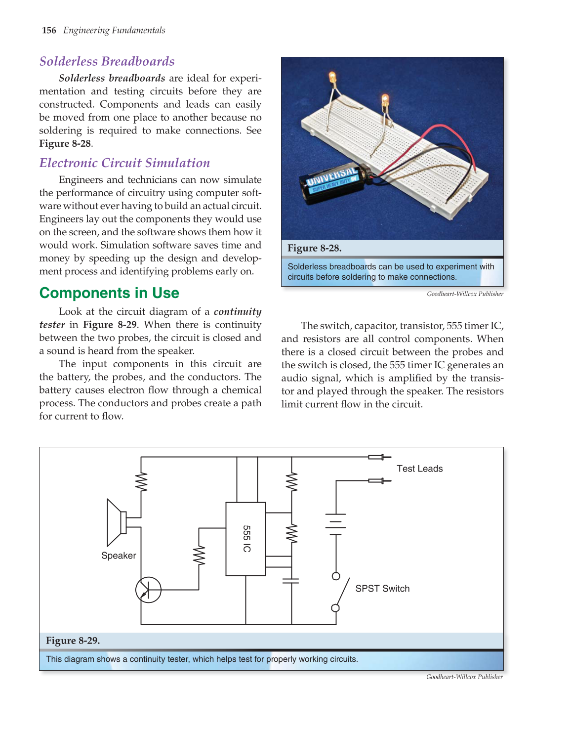
Look at the circuit diagram of a continuity
tester in Figure 8-29. When there is continuity
between the two probes, the circuit is closed and
a sound is heard from the speaker.
The input components in this circuit are
the battery, the probes, and the conductors. The
battery causes electron fl ow through a chemical
process. The conductors and probes create a path
for current to fl ow.
The switch, capacitor, transistor, 555 timer IC,
and resistors are all control components. When
there is a closed circuit between the probes and
the switch is closed, the 555 timer IC generates an
audio signal, which is amplifi ed by the transis-
tor and played through the speaker. The resistors
limit current fl ow in the circuit.
Solderless breadboards can be used to experiment with
circuits before soldering to make connections.
Figure 8-28.
Goodheart-Willcox Publisher
SPST Switch
555
IC
Test Leads
Speaker
Figure 8-29.
This diagram shows a continuity tester, which helps test for properly working circuits.
Goodheart-Willcox Publisher
