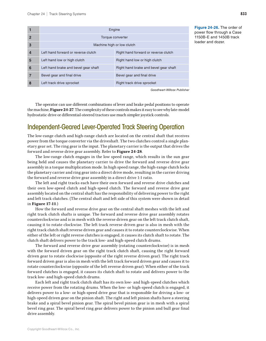
Copyright Goodheart-Willcox Co., Inc. 833 Chapter 24 ∣ Track Steering Systems The operator can use different combinations of lever and brake pedal positions to operate the machine, Figure 24-27. The complexity of these controls makes it easy to see why late-model hydrostatic drive or differential-steered tractors use much simpler joystick controls. Independent-Geared Lever-Operated Track Steering Operation The low-range clutch and high-range clutch are located on the central shaft that receives power from the torque converter via the driveshaft. The two clutches control a single plan- etary gear set. The ring gear is the input. The planetary carrier is the output that drives the forward and reverse drive gear assembly. Refer to Figure 24-28. The low-range clutch engages in the low speed range, which results in the sun gear being held and causes the planetary carrier to drive the forward and reverse drive gear assembly in a torque multiplication mode. In high speed range, the high-range clutch locks the planetary carrier and ring gear into a direct drive mode, resulting in the carrier driving the forward and reverse drive gear assembly in a direct drive 1:1 ratio. The left and right tracks each have their own forward and reverse drive clutches and their own low-speed clutch and high-speed clutch. The forward and reverse drive gear assembly located on the central shaft has the responsibility of delivering power to the right and left track clutches. (The central shaft and left side of this system were shown in detail in Figure 17-11.) How the forward and reverse drive gear on the central shaft meshes with the left and right track clutch shafts is unique. The forward and reverse drive gear assembly rotates counterclockwise and is in mesh with the reverse driven gear on the left track clutch shaft, causing it to rotate clockwise. The left track reverse driven gear is also in mesh with the right track clutch shaft reverse driven gear and causes it to rotate counterclockwise. When either of the left or right reverse clutches is engaged, it causes its clutch shaft to rotate. The clutch shaft delivers power to the track low- and high-speed clutch drums. The forward and reverse drive gear assembly (rotating counterclockwise) is in mesh with the forward driven gear on the right track clutch shaft, causing the right forward driven gear to rotate clockwise (opposite of the right reverse driven gear). The right track forward driven gear is also in mesh with the left track forward driven gear and causes it to rotate counterclockwise (opposite of the left reverse driven gear). When either of the track forward clutches is engaged, it causes its clutch shaft to rotate and delivers power to the track low- and high-speed clutch drums. Each left and right track clutch shaft has its own low- and high-speed clutches which receive power from the rotating drums. When the low- or high-speed clutch is engaged, it delivers power to a low- or high-speed drive gear that is responsible for driving a low- or high-speed driven gear on the pinion shaft. The right and left pinion shafts have a steering brake and a spiral bevel pinion gear. The spiral bevel pinion gear is in mesh with a spiral bevel ring gear. The spiral bevel ring gear delivers power to the pinion and bull gear final drive assembly. 1 Engine 2 Torque converter 3 Machine high or low clutch 4 Left hand forward or reverse clutch Right hand forward or reverse clutch 5 Left hand low or high clutch Right hand low or high clutch 6 Left hand brake and bevel gear shaft Right hand brake and bevel gear shaft 7 Bevel gear and final drive Bevel gear and final drive 8 Left track drive sprocket Right track drive sprocket Goodheart-Willcox Publisher Figure 24-26. The order of power flow through a Case 1150B-E and 1450B track loader and dozer.
