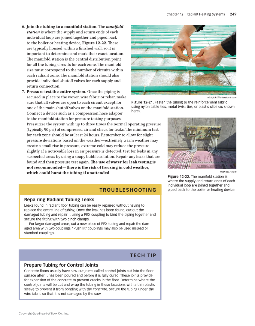
Copyright Goodheart-Willcox Co., Inc. Chapter 12 Radiant Heating Systems 249 6. Join the tubing to a manifold station. The manifold station is where the supply and return ends of each individual loop are joined together and piped back to the boiler or heating device, Figure 12-22. These are typically housed within a finished wall, so it is important to determine and mark their exact location. The manifold station is the central distribution point for all the tubing circuits for each zone. The manifold size must correspond to the number of circuits within each radiant zone. The manifold station should also provide individual shutoff valves for each supply and return connection. 7. Pressure test the entire system. Once the piping is secured in place to the woven wire fabric or rebar, make sure that all valves are open to each circuit except for one of the main shutoff valves on the manifold station. Connect a device such as a compression hose adapter to the manifold station for pressure testing purposes. Pressurize the system with up to three times the normal operating pressure (typically 90 psi) of compressed air and check for leaks. The minimum test for each zone should be at least 24 hours. Remember to allow for slight pressure deviations based on the weather—extremely warm weather may create a small rise in pressure, extreme cold may reduce the pressure slightly. If a noticeable loss in air pressure is detected, test for leaks in any suspected areas by using a soapy bubble solution. Repair any leaks that are found and then pressure test again. The use of water for leak testing is not recommended—there is the risk of freezing in cold weather, which could burst the tubing if unattended. TROUBLESHOOTING Repairing Radiant Tubing Leaks Leaks found in radiant floor tubing can be easily repaired without having to replace the entire line of tubing. Once the leak has been found, cut out the damaged tubing and repair it using a PEX coupling to bind the piping together and secure the fitting with two cinch clamps. For larger damaged areas, cut a new piece of PEX tubing and repair the dam- aged area with two couplings. “Push fit” couplings may also be used instead of standard couplings. TECH TIP Prepare Tubing for Control Joints Concrete floors usually have saw-cut joints called control joints cut into the floor surface after it has been poured and before it is fully cured. These joints provide for expansion of the concrete to prevent cracks in the floor. Determine where the control joints will be cut and wrap the tubing in these locations with a thin plastic sleeve to prevent it from bonding with the concrete. Secure the tubing under the wire fabric so that it is not damaged by the saw. nikkytok/Shutterstock.com Figure 12-21. Fasten the tubing to the reinforcement fabric using nylon cable ties, metal twist ties, or plastic clips (as shown here). Michael Helsel Figure 12-22. The manifold station is where the supply and return ends of each individual loop are joined together and piped back to the boiler or heating device.