346 Section 3 Fundamentals of Electricity and Electronics
Meter Connections
As you may recall, a voltmeter measures elec-
trical pressure, or voltage (V). A voltmeter is con-
nected in parallel with the circuit being tested. The
circuit’s power source must operate the voltmeter.
See Figure 22-16A.
CAUTION
Many hybrid drive systems operate on
high voltage. Use only test instruments
rated for high voltage when testing
high-voltage hybrid drive trains. High-voltage test
equipment has thicker internal insulation to prevent
internal electric arcs that would damage a low-
voltage test instrument.
An ohmmeter measures the resistance to current
in ohms (Ω). Power must be disconnected from the
component or portion of the circuit being tested.
Then the ohmmeter can be connected to each end of
a wire or component to check its internal resistance.
This is shown in Figure 22-16B.
An ammeter measures current in amps (A). A con-
ventional ammeter must be connected in series with
the circuit being tested. All circuit current must pass
through the ammeter. See Figure 22-16C. However,
inductive ammeters have a clip-on pickup that fi ts
over the wire insulation, as shown in Figure 22-16D.
The pickup senses and measures the magnetic fi eld
around the wire, which is proportional to the cur-
rent in the wire. The ammeter calculates and dis-
plays the reading in amps. An inductive pickup is
a handy meter attachment for analyzing charging
systems and hybrid power system operation. Most
meters connected in series will not read more than a
few amps without an inductive pickup.
Meter Controls
Most digital and digital-analog multimeters have
a large function knob that can be rotated to select the
type of electrical reading to be taken. The function
knob can select a reading in volts dc or ac, amps dc
or ac, and ohms. It may also have other settings, such
as rpm and diode testing. See Figure 22-17. Meter
control buttons are usually provided to allow you
to select other function variables: zero meter, mini-
mum/maximum readings during the test, range,
hold, duty cycle (percent on and off), and sound alert.
Most multimeters also have different test lead sock-
ets or holes, as shown in Figure 22-17. Each socket is
for a different type or range of measurement.
Most digital meters are auto ranging—they
automatically change to the correct scale. All you
have to do is set the meter knob for volts, amps, or
ohms, and the meter adjusts itself automatically to
the correct range. For example, a digital meter might
display a “k” next to the number readout when
you are measuring a high resistance, as shown in
Figure 22-18. This means the meter is displaying the
value in kilohms. A reading of 9.27 kΩ equals 9270
ohms. An “M” next to the readout means the value
is displayed in megohms. If no prefi x is shown, the
reading is in ohms.
Tech Tip
To read a meter correctly, you must
understand the electrical multipliers shown on
the meter display. The prefi xes used on digital
multimeters are standard for electrical units.
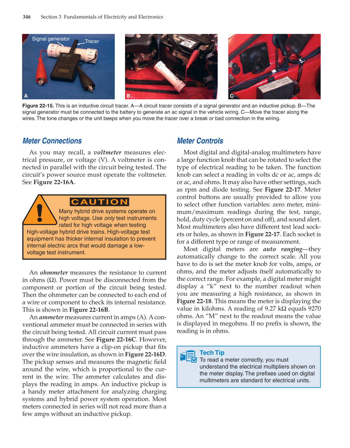
Figure 22-15. This is an inductive circuit tracer. A—A circuit tracer consists of a signal generator and an inductive pickup. B—The
signal generator must be connected to the battery to generate an ac signal in the vehicle wiring. C—Move the tracer along the
wires. The tone changes or the unit beeps when you move the tracer over a break or bad connection in the wiring.
Tracer
Signal generator
A B C
