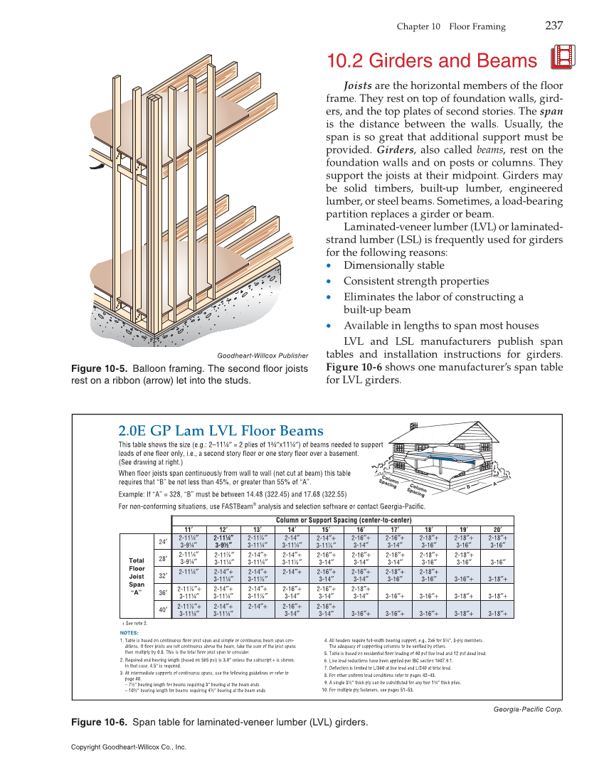
Chapter 10 Floor Framing 237 10.2 Girders and Beams Joists are the horizontal members of the floor frame. They rest on top of foundation walls, gird- ers, and the top plates of second stories. The span is the distance between the walls. Usually, the span is so great that additional support must be provided. Girders, also called beams, rest on the foundation walls and on posts or columns. They support the joists at their midpoint. Girders may be solid timbers, built-up lumber, engineered lumber, or steel beams. Sometimes, a load-bearing partition replaces a girder or beam. Laminated-veneer lumber (LVL) or laminated- strand lumber (LSL) is frequently used for girders for the following reasons: • Dimensionally stable • Consistent strength properties • Eliminates the labor of constructing a built-up beam • Available in lengths to span most houses LVL and LSL manufacturers publish span tables and installation instructions for girders. Figure 10-6 shows one manufacturer’s span table for LVL girders. Goodheart-Willcox Publisher Figure 10-5. Balloon framing. The second floor joists rest on a ribbon (arrow) let into the studs. 2.0E GP Lam LVL Floor Beams Column Spacing Column Spacing B A NOTES: 1. Table is based on continuous floor joist span and simple or continuous beam span con- ditions. If floor joists are not continuous above the beam, take the sum of the joist spans then multiply by 0.8. This is the total floor joist span to consider. 2. Required end bearing length (based on 565 psi) is 3.0″ unless the subscript + is shown. In that case, 4.5″ is required. 3. At intermediate supports of continuous spans, use the following guidelines or refer to page 40. – 7½″ bearing length for beams requiring 3″ bearing at the beam ends – 10½″ bearing length for beams requiring 4½″ bearing at the beam ends Column or Support Spacing (center-to-center) 24′ Total Floor Joist Span “A” + See note 2. This table shows the size (e.g.: 2–11¼″ = 2 plies of 1¾″x11¼″) of beams needed to support loads of one floor only, i.e., a second story floor or one story floor over a basement. (See drawing at right.) When floor joists span continuously from wall to wall (not cut at beam) this table requires that “B” be not less than 45%, or greater than 55% of “A”. Example: If “A” = 328, “B” must be between 14.48 (322.45) and 17.68 (322.55) For non-conforming situations, use FASTBeam® analysis and selection software or contact Georgia-Pacific. 28′ 32′ 36′ 40′ 11′ 2-11¼″ 3-9¼″ 2-11¼″ 3-9¼″ 2-11¼″ 2-11 ″+ 3-11¼″ 7 8 2-11 ″+ 3-11¼″ 7 8 12′ 2-11¼″ 3-9½″ 2-11¼ ″ 3-9½ ″ 2-14″ 3-11¼″ 2-14″+ 3-11¼″ 2-14″+ 3-11¼″ 2-11 ″ 3-11¼″ 7 8 2-14″+ 3-11¼″ 2-11 ″ 3-11¼″ 7 8 2-14″+ 3-11¼″ 2-14″+ 3-11 ″ 7 8 2-14″+ 3-11 ″ 7 8 2-14″+ 13′ 14′ 2-14″+ 3-11 ″ 7 8 2-14″+ 2-16″+ 3-14″ 2-16″+ 3-14″ 2-16″+ 3-14″ 2-16″+ 3-14″ 2-18″+ 3-14″ 3-16″+ 2-14″+ 3-11 ″ 7 8 2-16″+ 3-14″ 2-16″+ 3-14″ 2-16″+ 3-14″ 2-16″+ 3-14″ 15′ 2-16″+ 3-14″ 16′ 2-16″+ 3-14″ 2-18″+ 3-16″ 3-16″+ 3-16″+ 2-16″+ 3-14″ 17′ 2-18″+ 3-16″ 2-18″+ 3-16″ 3-16″+ 3-16″+ 2-18″+ 3-16″ 18′ 2-18″+ 3-16″ 3-16″+ 3-18″+ 3-18″+ 2-18″+ 3-16″ 19′ 2-18″+ 3-16″ 3-18″+ 3-18″+ 3-18″+ 3-16″ 20′ 4. All headers require full-width bearing support, e.g., 2x6 for 5¼″, 3-ply members. The adequacy of supporting columns to be verified by others. 5. Table is based on residential floor loading of 40 psf live load and 12 psf dead load. 6. Live load reductions have been applied per IBC section 1607.9.1. 7. Deflection is limited to L/360 at live load and L/240 at total load. 8. For other uniform load conditions refer to pages 42–43. 9. A single 3½″ thick ply can be substituted for any two 1¾″ thick plies. 10. For multiple ply fasteners, see pages 51–53. Georgia-Pacific Corp. Figure 10-6. Span table for laminated-veneer lumber (LVL) girders. Copyright Goodheart-Willcox Co., Inc.