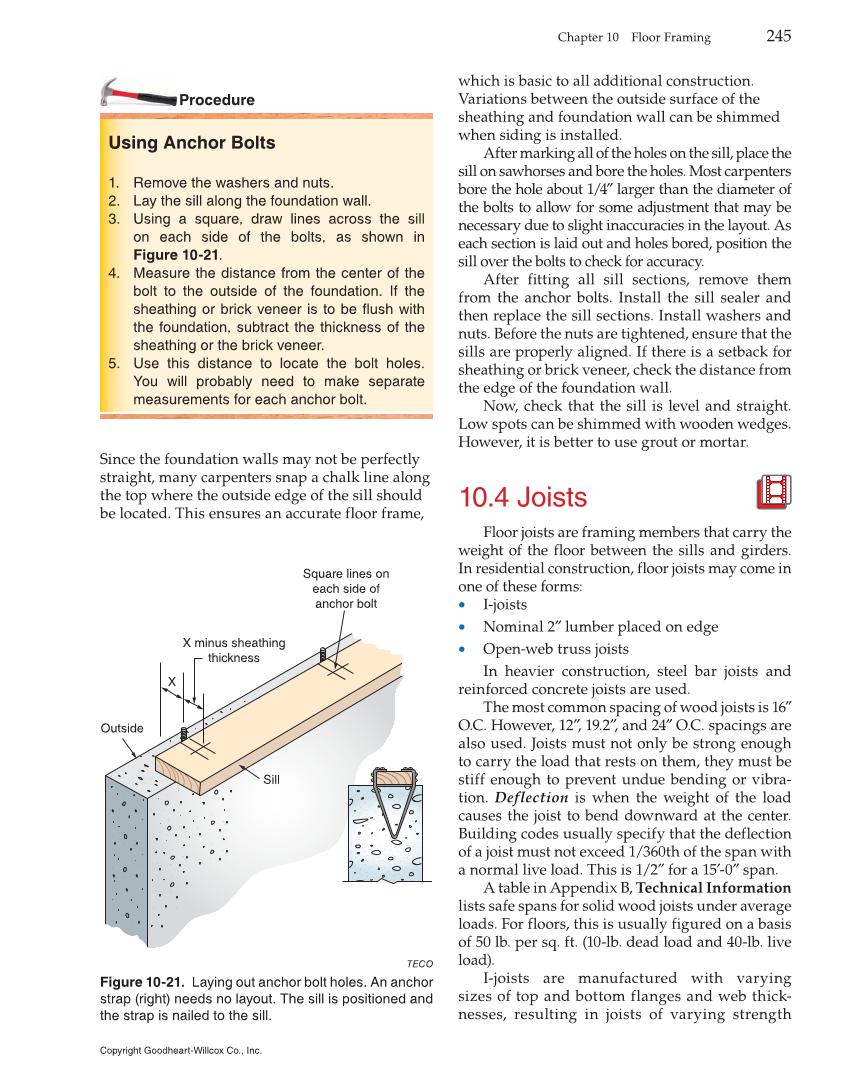
Chapter 10 Floor Framing 245 Procedure Using Anchor Bolts 1. Remove the washers and nuts. 2. Lay the sill along the foundation wall. 3. Using a square, draw lines across the sill on each side of the bolts, as shown in Figure 10-21. 4. Measure the distance from the center of the bolt to the outside of the foundation. If the sheathing or brick veneer is to be flush with the foundation, subtract the thickness of the sheathing or the brick veneer. 5. Use this distance to locate the bolt holes. You will probably need to make separate measurements for each anchor bolt. Since the foundation walls may not be perfectly straight, many carpenters snap a chalk line along the top where the outside edge of the sill should be located. This ensures an accurate floor frame, which is basic to all additional construction. Variations between the outside surface of the sheathing and foundation wall can be shimmed when siding is installed. After marking all of the holes on the sill, place the sill on sawhorses and bore the holes. Most carpenters bore the hole about 1/4″ larger than the diameter of the bolts to allow for some adjustment that may be necessary due to slight inaccuracies in the layout. As each section is laid out and holes bored, position the sill over the bolts to check for accuracy. After fitting all sill sections, remove them from the anchor bolts. Install the sill sealer and then replace the sill sections. Install washers and nuts. Before the nuts are tightened, ensure that the sills are properly aligned. If there is a setback for sheathing or brick veneer, check the distance from the edge of the foundation wall. Now, check that the sill is level and straight. Low spots can be shimmed with wooden wedges. However, it is better to use grout or mortar. 10.4 Joists Floor joists are framing members that carry the weight of the floor between the sills and girders. In residential construction, floor joists may come in one of these forms: • I-joists • Nominal 2″ lumber placed on edge • Open-web truss joists In heavier construction, steel bar joists and reinforced concrete joists are used. The most common spacing of wood joists is 16″ O.C. However, 12″, 19.2″, and 24″ O.C. spacings are also used. Joists must not only be strong enough to carry the load that rests on them, they must be stiff enough to prevent undue bending or vibra- tion. Deflection is when the weight of the load causes the joist to bend downward at the center. Building codes usually specify that the deflection of a joist must not exceed 1/360th of the span with a normal live load. This is 1/2″ for a 15′-0″ span. A table in Appendix B, Technical Information lists safe spans for solid wood joists under average loads. For floors, this is usually figured on a basis of 50 lb. per sq. ft. (10-lb. dead load and 40-lb. live load). I-joists are manufactured with varying sizes of top and bottom flanges and web thick- nesses, resulting in joists of varying strength Outside Sill Square lines on each side of anchor bolt X minus sheathing thickness X TECO Figure 10-21. Laying out anchor bolt holes. An anchor strap (right) needs no layout. The sill is positioned and the strap is nailed to the sill. Copyright Goodheart-Willcox Co., Inc.