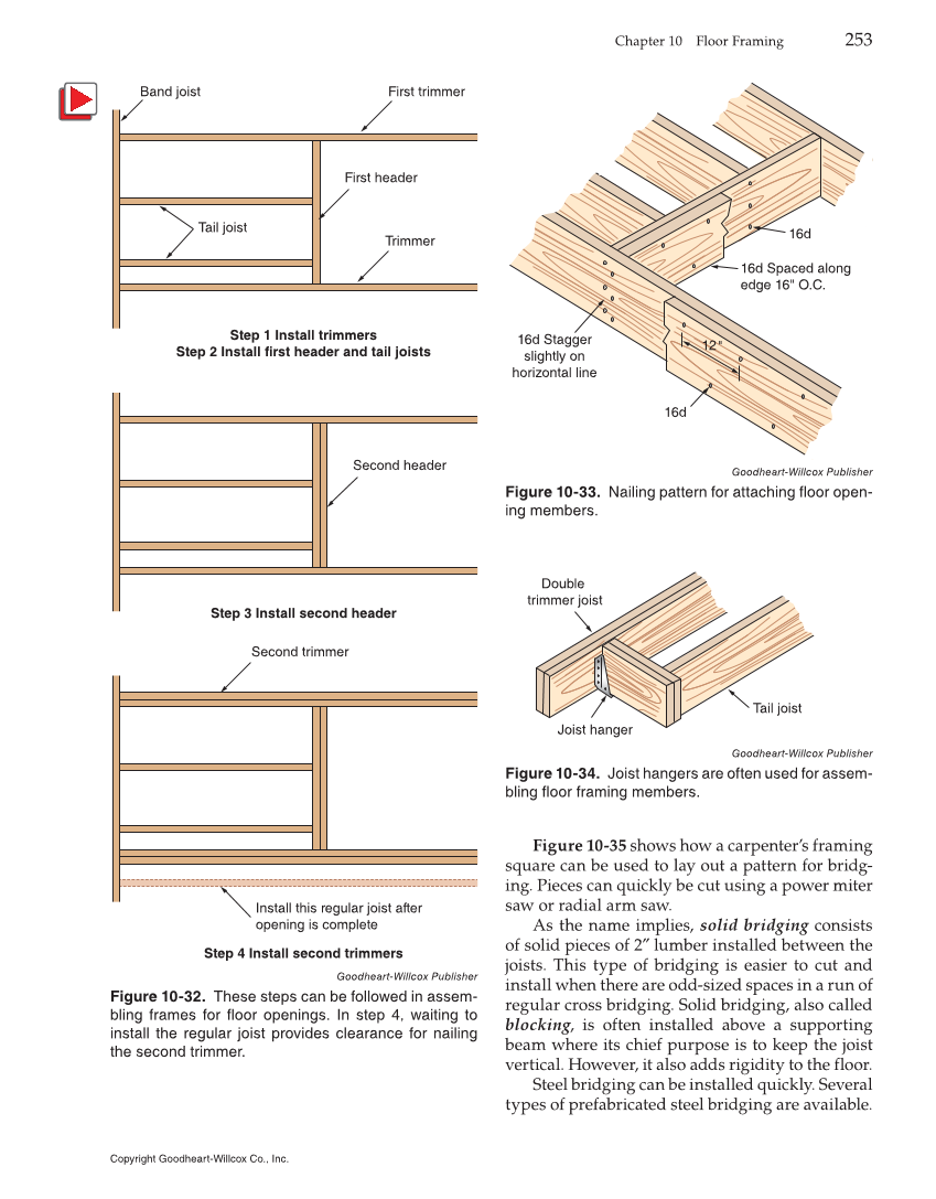
Chapter 10 Floor Framing 253 Figure 10-35 shows how a carpenter’s framing square can be used to lay out a pattern for bridg- ing. Pieces can quickly be cut using a power miter saw or radial arm saw. As the name implies, solid bridging consists of solid pieces of 2″ lumber installed between the joists. This type of bridging is easier to cut and install when there are odd-sized spaces in a run of regular cross bridging. Solid bridging, also called blocking, is often installed above a supporting beam where its chief purpose is to keep the joist vertical. However, it also adds rigidity to the floor. Steel bridging can be installed quickly. Several types of prefabricated steel bridging are available. Band joist First trimmer Tail joist Trimmer First header Step 1 Install trimmers Step 2 Install first header and tail joists Second header Step 3 Install second header Second trimmer Install this regular joist after opening is complete Step 4 Install second trimmers Goodheart-Willcox Publisher Figure 10-32. These steps can be followed in assem- bling frames for floor openings. In step 4, waiting to install the regular joist provides clearance for nailing the second trimmer. 12 16d 16d Spaced along edge 16" O.C. 16d Stagger slightly on horizontal line 16d Goodheart-Willcox Publisher Figure 10-33. Nailing pattern for attaching floor open- ing members. Tail joist Joist hanger Double trimmer joist Goodheart-Willcox Publisher Figure 10-34. Joist hangers are often used for assem- bling floor framing members. Copyright Goodheart-Willcox Co., Inc.