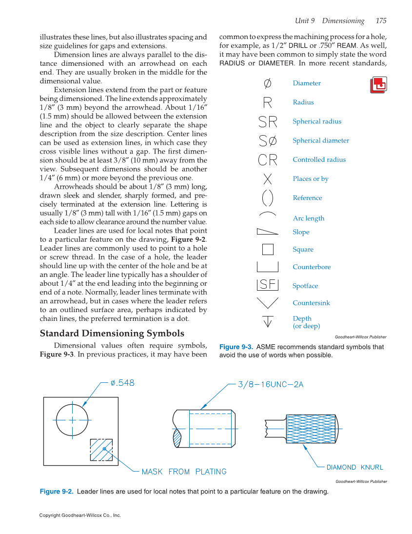
Unit 9 Dimensioning 175 Copyright Goodheart-Willcox Co., Inc. illustrates these lines, but also illustrates spacing and size guidelines for gaps and extensions. Dimension lines are always parallel to the dis- tance dimensioned with an arrowhead on each end. They are usually broken in the middle for the dimensional value. Extension lines extend from the part or feature being dimensioned. The line extends approximately 1/8″ (3 mm) beyond the arrowhead. About 1/16″ (1.5 mm) should be allowed between the extension line and the object to clearly separate the shape description from the size description. Center lines can be used as extension lines, in which case they cross visible lines without a gap. The first dimen- sion should be at least 3/8″ (10 mm) away from the view. Subsequent dimensions should be another 1/4″ (6 mm) or more beyond the previous one. Arrowheads should be about 1/8″ (3 mm) long, drawn sleek and slender, sharply formed, and pre- cisely terminated at the extension line. Lettering is usually 1/8″ (3 mm) tall with 1/16″ (1.5 mm) gaps on each side to allow clearance around the number value. Leader lines are used for local notes that point to a particular feature on the drawing, Figure 9-2. Leader lines are commonly used to point to a hole or screw thread. In the case of a hole, the leader should line up with the center of the hole and be at an angle. The leader line typically has a shoulder of about 1/4″ at the end leading into the beginning or end of a note. Normally, leader lines terminate with an arrowhead, but in cases where the leader refers to an outlined surface area, perhaps indicated by chain lines, the preferred termination is a dot. Standard Dimensioning Symbols Dimensional values often require symbols, Figure 9-3. In previous practices, it may have been common to express the machining process for a hole, for example, as 1/2″ DRILL or .750″ REAM. As well, it may have been common to simply state the word RADIUS or DIAMETER. In more recent standards, Goodheart-Willcox Publisher Figure 9-2. Leader lines are used for local notes that point to a particular feature on the drawing. Goodheart-Willcox Publisher Figure 9-3. ASME recommends standard symbols that avoid the use of words when possible. Diameter Radius Spherical radius Spherical diameter Controlled radius Places or by Reference Arc length Slope Square Counterbore Countersink Depth (or deep) Spotface