Chapter 1 Introduction to Three-Dimensional Modeling
25
NOTE N OT OT TE
Selecting an orthographic view of a model using one of the methods
described previously produces a plan view, but it may not achieve
the results you desire. Three-dimensional models can be displayed in
AutoCAD using either parallel or perspective projection. Displaying
a plan view in either projection is possible. However, a true plan view,
as used in 2D orthographic projections, can only be created when the
model is displayed as a parallel projection. You can quickly change
the display from perspective to parallel, or vice versa, by picking
either
Parallel
or
Perspective
in the
View Controls
fl yout in the view- fl
port controls. The current projection is checked in the fl yout. fl
Exercise 1-2
Complete the exercise on the companion website.
www.g-wlearning.com/CAD
Introduction to the View Cube
You are not limited to the preset isometric viewpoints. In fact, you can view a 3D
object from an unlimited number of viewpoints. The view cube allows you to display
all of the preset isometric and orthographic views without making menu or ribbon
selections. It also provides quick access to additional pictorial views and easy dynamic
manipulation of all orthographic views. It allows you to dynamically rotate the view
of the objects to create a new viewpoint.
The view cube is displayed by default in the upper-right corner of the drawing
window. See Figure 1-13. It can be quickly turned on or off by selecting
ViewCube
from the
Viewport Controls
fl yout in the viewport controls. Refer to fl Figure 1-10A. The
NAVVCUBE
command controls the display of the view cube.
NAVVCUBE
Ribbon
View
User Interface
User Interface
Type
NAVVCUBE
CUBE
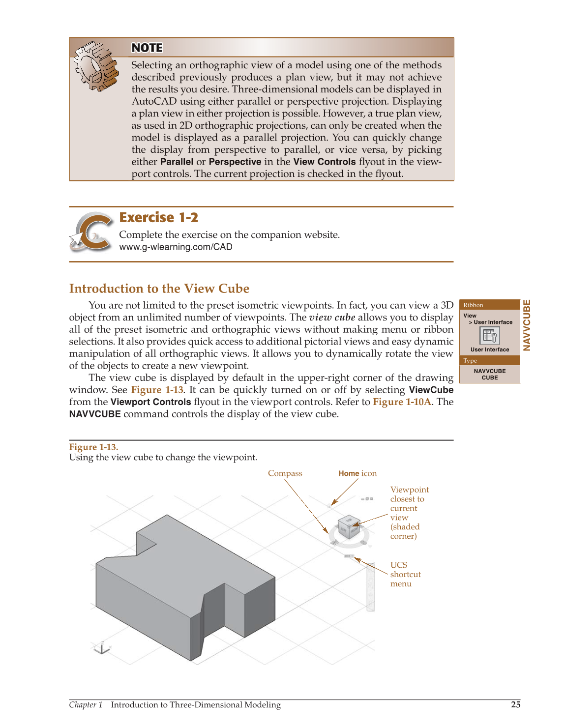
Figure 1-13.
Using the view cube to change the viewpoint.
UCS
shortcut
menu
Viewpoint
closest to
current
view
(shaded
corner)
Compass
Home
icon