202
AutoCAD and Its Applications—Advanced
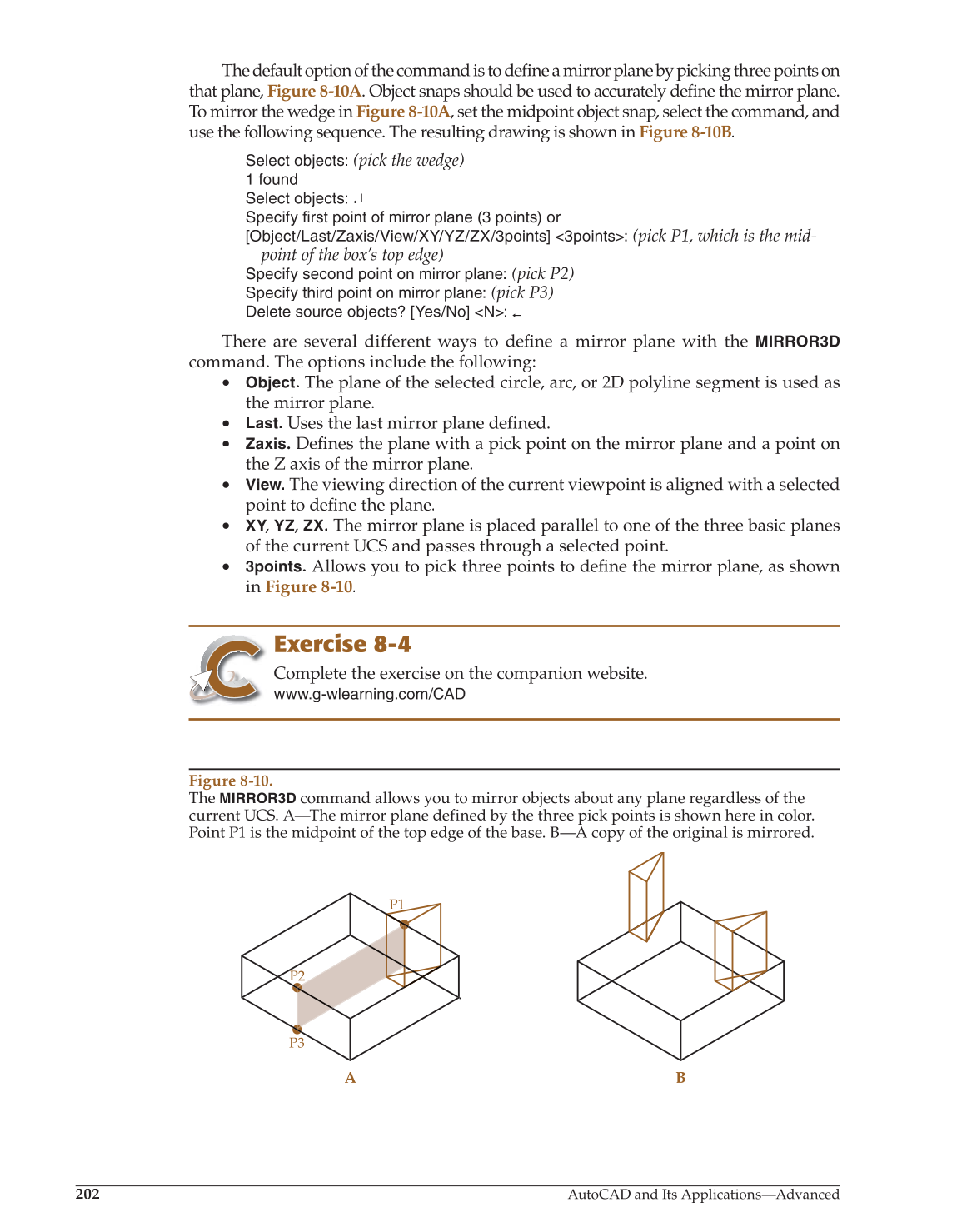
The default option of the command is to defi a mirror plane by picking three points on fine
that plane, Figure 8-10A. Object snaps should be used to accurately define the mirror plane. fi
To mirror the wedge in Figure 8-10A, set the midpoint object snap, select the command, and A
use the following sequence. The resulting drawing is shown in Figure 8-10B.
Select objects:
(pick the wedge)
1 found
Select objects: ↵
Specify first point of mirror plane (3 points) or
[Object/Last/Zaxis/View/XY/YZ/ZX/3points] 3points:
(pick P1, which is the mid-
point of the box’s top edge)
Specify second point on mirror plane:
(pick P2)
Specify third point on mirror plane:
(pick P3)
Delete source objects? [Yes/No] N: ↵
There are several different ways to define a mirror plane with the fi
MIRROR3D
command. The options include the following:
• Object. The plane of the selected circle, arc, or 2D polyline segment is used as
the mirror plane.
• Last. Uses the last mirror plane defined.fi
• Zaxis. Defi the plane with a pick point on the mirror plane and a point on fines
the Z axis of the mirror plane.
• View. The viewing direction of the current viewpoint is aligned with a selected
point to defi the plane. fine
• XY,
Y Y
YZ, ZX. The mirror plane is placed parallel to one of the three basic planes
of the current UCS and passes through a selected point.
• 3points. Allows you to pick three points to define the mirror plane, as shown fi
in Figure 8-10.
Exercise 8-4
Complete the exercise on the companion website.
www.g-wlearning.com/CAD
Figure 8-10.
The
MIRROR3D
command allows you to mirror objects about any plane regardless of the
current UCS. A—The mirror plane defined by the three pick points is shown here in color.
Point P1 is the midpoint of the top edge of the base. B—A copy of the original is mirrored.
A B
P1
P2
P3