206
AutoCAD and Its Applications—Advanced
To create a 3D polar array, select the
ARRAYPOLAR
command. Select the object to
array and press [Enter]. Then, pick the center point of the array or use the
Axis of rota-
tion
option to select a centerline axis. The
Axis of rotation
option allows you to select
a centerline axis that is different from the Z axis of the current UCS. Using this option
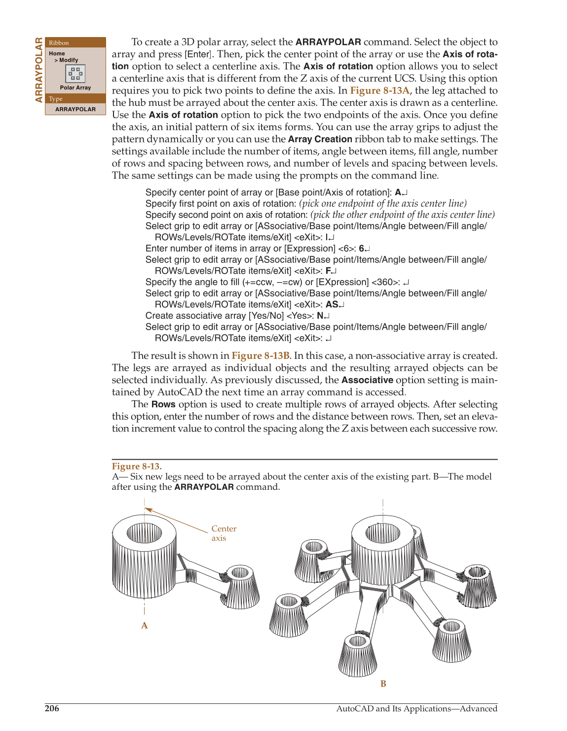
requires you to pick two points to define the axis. In fi Figure 8-13A, the leg attached to
the hub must be arrayed about the center axis. The center axis is drawn as a centerline.
Use the
Axis of rotation
option to pick the two endpoints of the axis. Once you definefi
the axis, an initial pattern of six items forms. You can use the array grips to adjust the
pattern dynamically or you can use the
Array Creation
ribbon tab to make settings. The
settings available include the number of items, angle between items, fi ll angle, number fi
of rows and spacing between rows, and number of levels and spacing between levels.
The same settings can be made using the prompts on the command line.
Specify center point of array or [Base point/Axis of rotation]: A↵
Specify first point on axis of rotation:
(pick one endpoint of the axis center line)
Specify second point on axis of rotation:
(pick the other endpoint of the axis center line)
Select grip to edit array or [ASsociative/Base point/Items/Angle between/Fill angle/
ROWs/Levels/ROTate items/eXit] eXit: I↵
Enter number of items in array or [Expression] 6: 6↵
Select grip to edit array or [ASsociative/Base point/Items/Angle between/Fill angle/
ROWs/Levels/ROTate items/eXit] eXit: F↵ F F
Specify the angle to fill (+=ccw, –=cw) or [EXpression] 360: ↵
Select grip to edit array or [ASsociative/Base point/Items/Angle between/Fill angle/
ROWs/Levels/ROTate items/eXit] eXit: AS↵
Create associative array [Yes/No] Yes: N↵
Select grip to edit array or [ASsociative/Base point/Items/Angle between/Fill angle/
ROWs/Levels/ROTate items/eXit] eXit: ↵
The result is shown in Figure 8-13B. In this case, a non-associative array is created.
The legs are arrayed as individual objects and the resulting arrayed objects can be
selected individually. As previously discussed, the
Associative
option setting is main-
tained by AutoCAD the next time an array command is accessed.
The
Rows
option is used to create multiple rows of arrayed objects. After selecting
this option, enter the number of rows and the distance between rows. Then, set an eleva-
tion increment value to control the spacing along the Z axis between each successive row.
ARRAYPOLAR
Ribbon
Home
Modify
Polar Array
Type
ARRAYPOLAR
Figure 8-13.
A— Six new legs need to be arrayed about the center axis of the existing part. B—The model
after using the
ARRAYPOLAR
command.
A
B
Center
axis