Chapter 8 Creating and Working with Solid Model Features
219
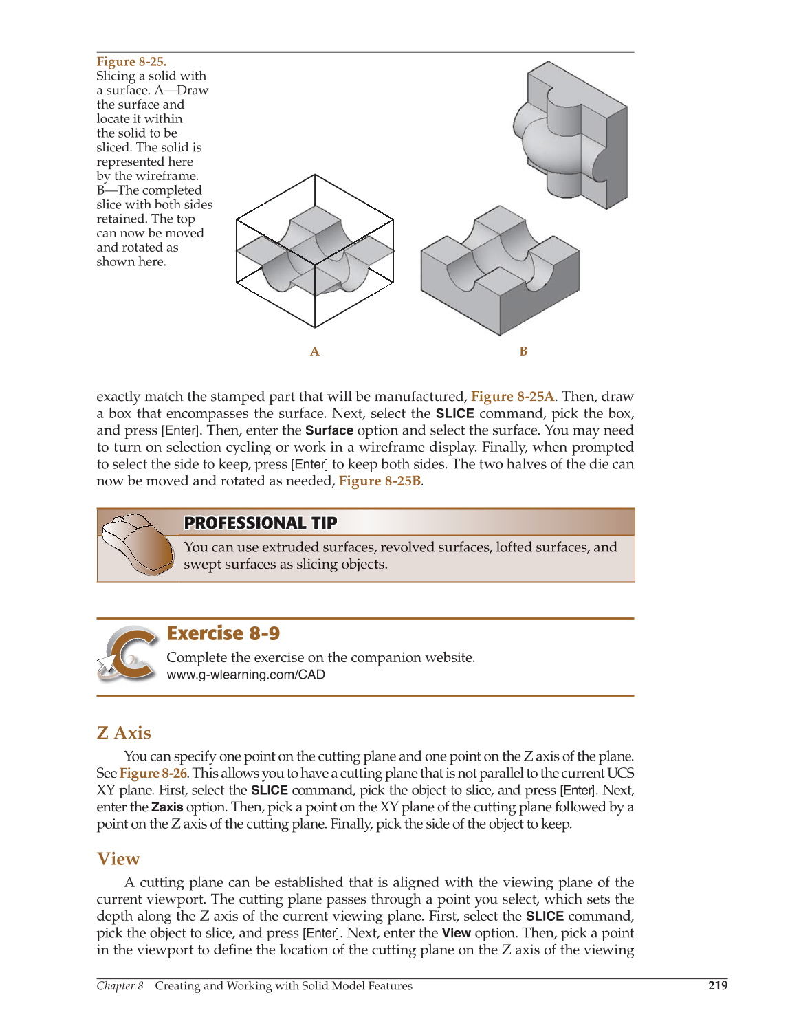
exactly match the stamped part that will be manufactured, Figure 8-25A. Then, draw
a box that encompasses the surface. Next, select the
SLICE
command, pick the box,
and press [Enter]. Then, enter the
Surface
option and select the surface. You may need
to turn on selection cycling or work in a wireframe display. Finally, when prompted
to select the side to keep, press
[Enter]
to keep both sides. The two halves of the die can
now be moved and rotated as needed, Figure 8-25B.
PROFESSIONAL P O TIP P PRO RO F FE S SS I O NA A L T P NA AL T TI P
You can use extruded surfaces, revolved surfaces, lofted surfaces, and
swept surfaces as slicing objects.
Exercise 8-9
Complete the exercise on the companion website.
www.g-wlearning.com/CAD
Z Axis
You can specify one point on the cutting plane and one point on the Z axis of the plane.
See Figure 8-26. This allows you to have a cutting plane that is not parallel to the current UCS
XY plane. First, select the
SLICE
command, pick the object to slice, and press [Enter]. Next,
enter the
Zaxis
option. Then, pick a point on the XY plane of the cutting plane followed by a
point on the Z axis of the cutting plane. Finally, pick the side of the object to keep.
View
A cutting plane can be established that is aligned with the viewing plane of the
current viewport. The cutting plane passes through a point you select, which sets the
depth along the Z axis of the current viewing plane. First, select the
SLICE
command,
pick the object to slice, and press [Enter]. Next, enter the
View
option. Then, pick a point
w
in the viewport to defi the location of the cutting plane on the Z axis of the viewing fine
Figure 8-25.
Slicing a solid with
a surface. A—Draw
the surface and
locate it within
the solid to be
sliced. The solid is
represented here
by the wireframe.
B—The completed
slice with both sides
retained. The top
can now be moved
and rotated as
shown here.
A B