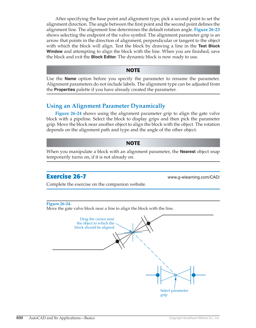
800 AutoCAD and Its Applications—Basics Copyright Goodheart-Willcox Co., Inc. After specifying the base point and alignment type, pick a second point to set the alignment direction. The angle between the fi rst point and the second point defi nes the alignment line. The alignment line determines the default rotation angle. Figure 26-23 shows selecting the endpoint of the valve symbol. The alignment parameter grip is an arrow that points in the direction of alignment, perpendicular or tangent to the object with which the block will align. Test the block by drawing a line in the Test Block Window and attempting to align the block with the line. When you are fi nished, save the block and exit the Block Editor. The dynamic block is now ready to use. NOTE NOTE Use the Name option before you specify the parameter to rename the parameter. Alignment parameters do not include labels. The alignment type can be adjusted from the Properties palette if you have already created the parameter. Using an Alignment Parameter Dynamically Figure 26-24 shows using the alignment parameter grip to align the gate valve block with a pipeline. Select the block to display grips and then pick the parameter grip. Move the block near another object to align the block with the object. The rotation depends on the alignment path and type and the angle of the other object. NOTE NOTE When you manipulate a block with an alignment parameter, the Nearest object snap temporarily turns on, if it is not already on. Exercise 26-7 www.g-wlearning.com/CAD/ Complete the exercise on the companion website. Figure 26-24. Move the gate valve block near a line to align the block with the line. Drag the cursor near the object to which the block should be aligned Select parameter grip