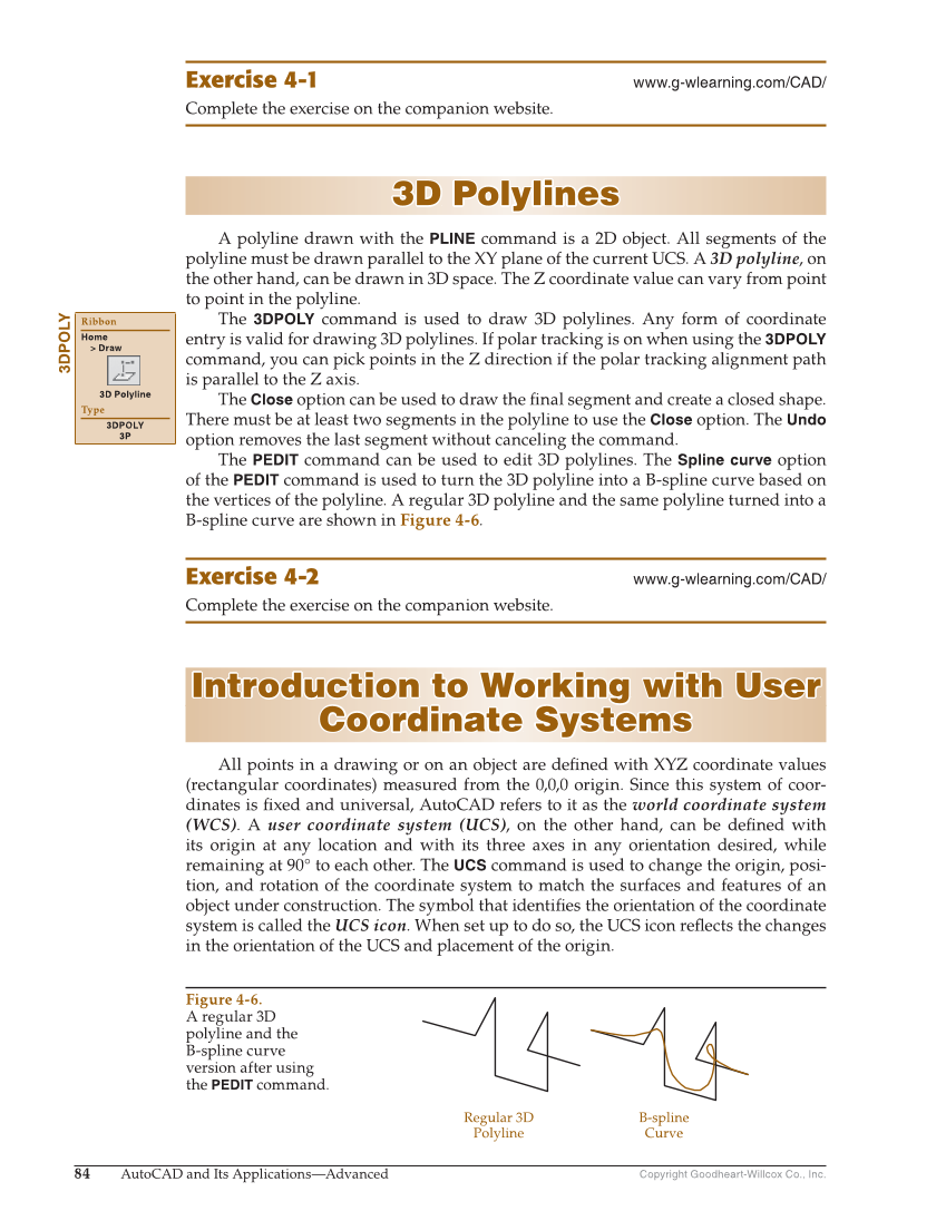
Copyright Goodheart-Willcox Co., Inc. 84 AutoCAD and Its Applications—Advanced Exercise 4-1 www.g-wlearning.com/CAD/ Complete the exercise on the companion website. 3D Polylines 3D Polylines A polyline drawn with the PLINE command is a 2D object. All segments of the polyline must be drawn parallel to the XY plane of the current UCS. A 3D polyline, on the other hand, can be drawn in 3D space. The Z coordinate value can vary from point to point in the polyline. The 3DPOLY command is used to draw 3D polylines. Any form of coordinate entry is valid for drawing 3D polylines. If polar tracking is on when using the 3DPOLY command, you can pick points in the Z direction if the polar tracking alignment path is parallel to the Z axis. The Close option can be used to draw the fi nal segment and create a closed shape. There must be at least two segments in the polyline to use the Close option. The Undo option removes the last segment without canceling the command. The PEDIT command can be used to edit 3D polylines. The Spline curve option of the PEDIT command is used to turn the 3D polyline into a B-spline curve based on the vertices of the polyline. A regular 3D polyline and the same polyline turned into a B-spline curve are shown in Figure 4-6. Exercise 4-2 www.g-wlearning.com/CAD/ Complete the exercise on the companion website. Introduction to Working with User Introduction to Working with User Coordinate Systems Coordinate Systems All points in a drawing or on an object are defi ned with XYZ coordinate values (rectangular coordinates) measured from the 0,0,0 origin. Since this system of coor- dinates is fi xed and universal, AutoCAD refers to it as the world coordinate system (WCS). A user coordinate system (UCS), on the other hand, can be defi ned with its origin at any location and with its three axes in any orientation desired, while remaining at 90° to each other. The UCS command is used to change the origin, posi- tion, and rotation of the coordinate system to match the surfaces and features of an object under construction. The symbol that identifi es the orientation of the coordinate system is called the UCS icon. When set up to do so, the UCS icon refl ects the changes in the orientation of the UCS and placement of the origin. 3DPOLY Ribbon Home Draw 3D Polyline Type 3DPOLY 3P Regular 3D Polyline B-spline Curve Figure 4-6. A regular 3D polyline and the B-spline curve version after using the PEDIT command.