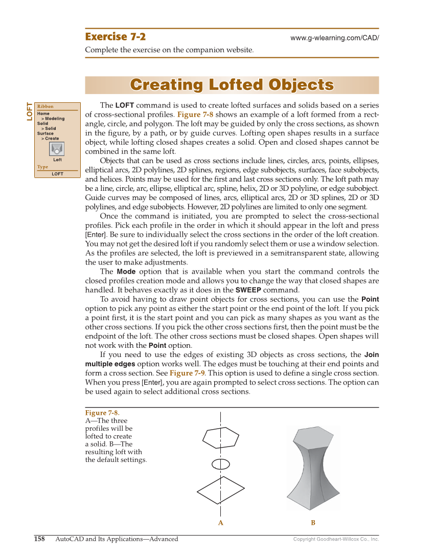
Copyright Goodheart-Willcox Co., Inc. 158 AutoCAD and Its Applications—Advanced Exercise 7-2 www.g-wlearning.com/CAD/ Complete the exercise on the companion website. Creating Lofted Objects Creating Lofted Objects The LOFT command is used to create lofted surfaces and solids based on a series of cross-sectional profi les. Figure 7-8 shows an example of a loft formed from a rect- angle, circle, and polygon. The loft may be guided by only the cross sections, as shown in the fi gure, by a path, or by guide curves. Lofting open shapes results in a surface object, while lofting closed shapes creates a solid. Open and closed shapes cannot be combined in the same loft. Objects that can be used as cross sections include lines, circles, arcs, points, ellipses, elliptical arcs, 2D polylines, 2D splines, regions, edge subobjects, surfaces, face subobjects, and helices. Points may be used for the fi rst and last cross sections only. The loft path may be a line, circle, arc, ellipse, elliptical arc, spline, helix, 2D or 3D polyline, or edge subobject. Guide curves may be composed of lines, arcs, elliptical arcs, 2D or 3D splines, 2D or 3D polylines, and edge subobjects. However, 2D polylines are limited to only one segment. Once the command is initiated, you are prompted to select the cross-sectional profi les. Pick each profi le in the order in which it should appear in the loft and press [Enter]. Be sure to individually select the cross sections in the order of the loft creation. You may not get the desired loft if you randomly select them or use a window selection. As the profi les are selected, the loft is previewed in a semitransparent state, allowing the user to make adjustments. The Mode option that is available when you start the command controls the closed profi les creation mode and allows you to change the way that closed shapes are handled. It behaves exactly as it does in the SWEEP command. To avoid having to draw point objects for cross sections, you can use the Point option to pick any point as either the start point or the end point of the loft. If you pick a point fi rst, it is the start point and you can pick as many shapes as you want as the other cross sections. If you pick the other cross sections fi rst, then the point must be the endpoint of the loft. The other cross sections must be closed shapes. Open shapes will not work with the Point option. If you need to use the edges of existing 3D objects as cross sections, the Join multiple edges option works well. The edges must be touching at their end points and form a cross section. See Figure 7-9. This option is used to defi ne a single cross section. When you press [Enter], you are again prompted to select cross sections. The option can be used again to select additional cross sections. LOFT Ribbon Home Modeling Solid Solid Surface Create Loft Type LOFT B A Figure 7-8. A—The three profiles will be lofted to create a solid. B—The resulting loft with the default settings.