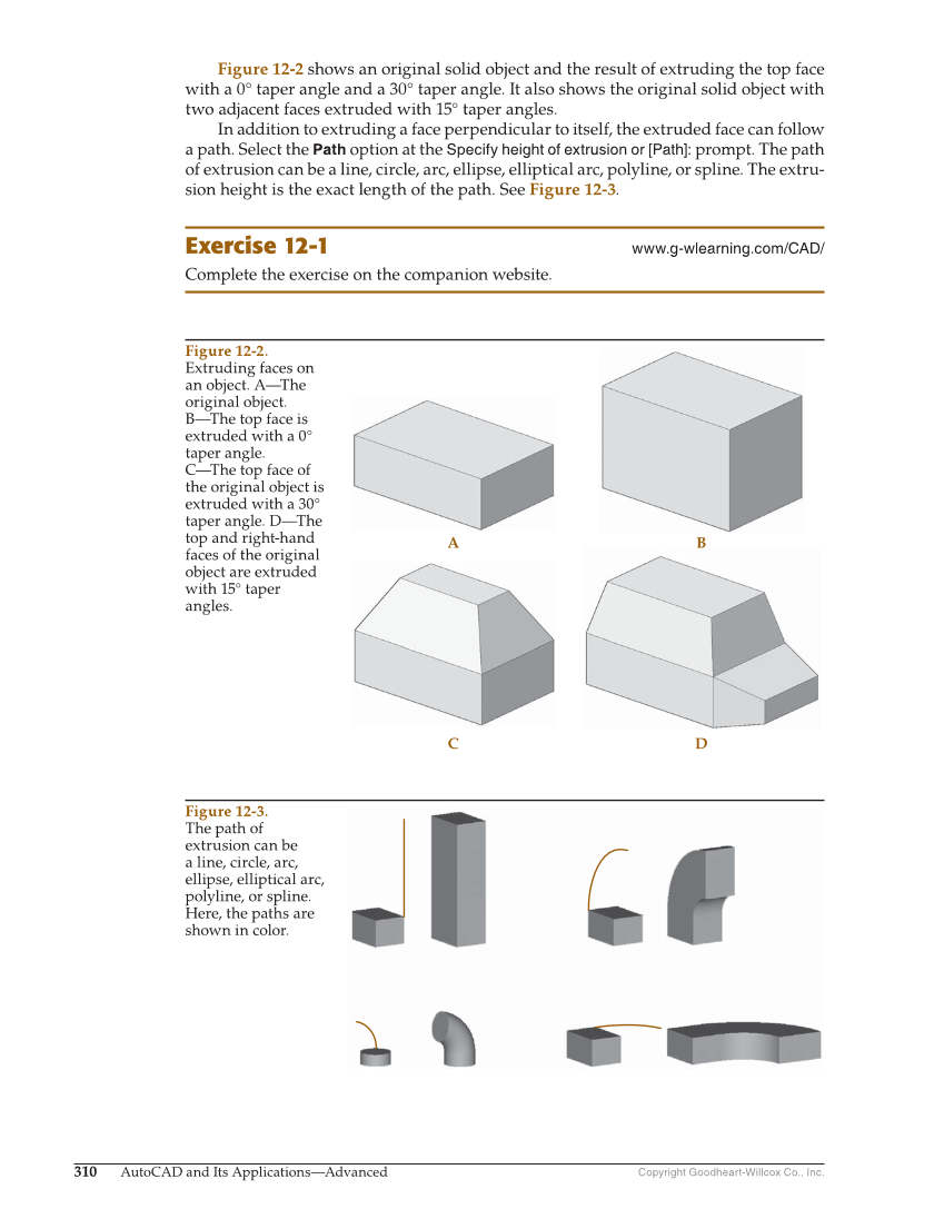
Copyright Goodheart-Willcox Co., Inc. 310 AutoCAD and Its Applications—Advanced Figure 12-2 shows an original solid object and the result of extruding the top face with a 0° taper angle and a 30° taper angle. It also shows the original solid object with two adjacent faces extruded with 15° taper angles. In addition to extruding a face perpendicular to itself, the extruded face can follow a path. Select the Path option at the Specify height of extrusion or [Path]: prompt. The path of extrusion can be a line, circle, arc, ellipse, elliptical arc, polyline, or spline. The extru- sion height is the exact length of the path. See Figure 12-3. Exercise 12-1 www.g-wlearning.com/CAD/ Complete the exercise on the companion website. A B C D Figure 12-2. Extruding faces on an object. A—The original object. B—The top face is extruded with a 0° taper angle. C—The top face of the original object is extruded with a 30° taper angle. D—The top and right-hand faces of the original object are extruded with 15° taper angles. Figure 12-3. The path of extrusion can be a line, circle, arc, ellipse, elliptical arc, polyline, or spline. Here, the paths are shown in color.