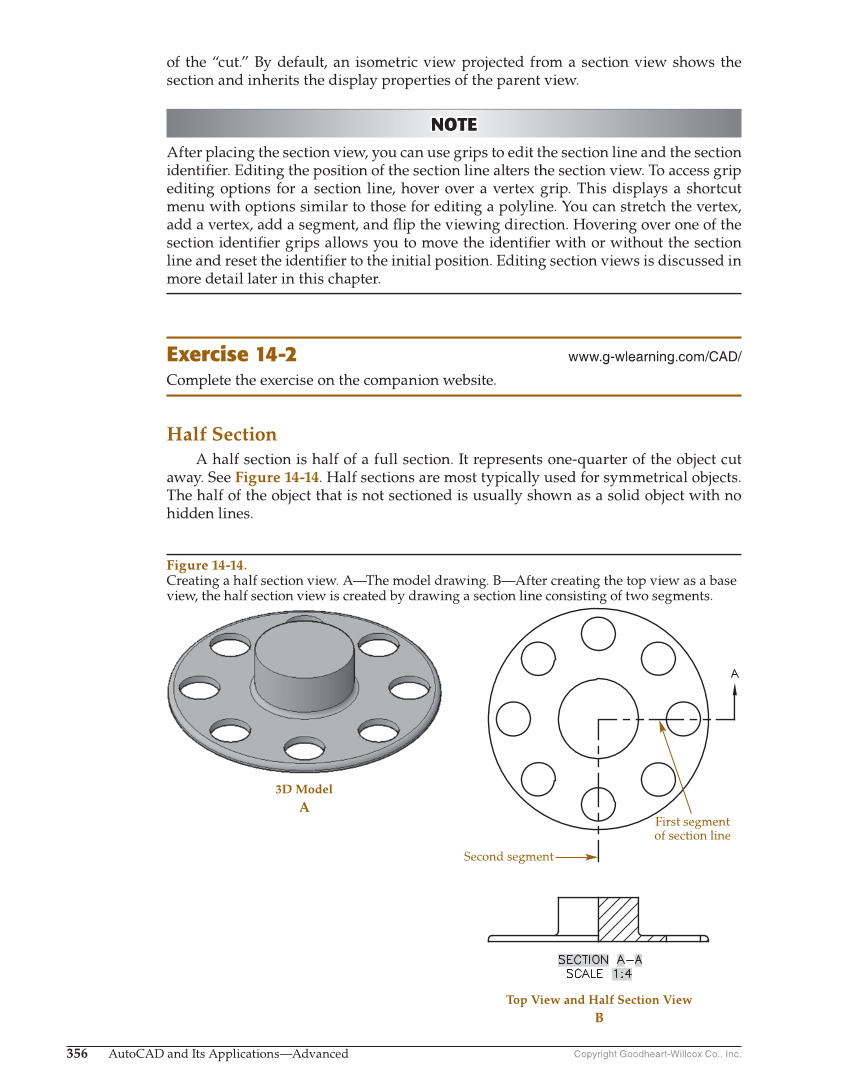
Copyright Goodheart-Willcox Co., Inc. 356 AutoCAD and Its Applications—Advanced of the “cut.” By default, an isometric view projected from a section view shows the section and inherits the display properties of the parent view. NOTE NOTE After placing the section view, you can use grips to edit the section line and the section identifi er. Editing the position of the section line alters the section view. To access grip editing options for a section line, hover over a vertex grip. This displays a shortcut menu with options similar to those for editing a polyline. You can stretch the vertex, add a vertex, add a segment, and fl ip the viewing direction. Hovering over one of the section identifi er grips allows you to move the identifi er with or without the section line and reset the identifi er to the initial position. Editing section views is discussed in more detail later in this chapter. Exercise 14-2 www.g-wlearning.com/CAD/ Complete the exercise on the companion website. Half Section A half section is half of a full section. It represents one-quarter of the object cut away. See Figure 14-14. Half sections are most typically used for symmetrical objects. The half of the object that is not sectioned is usually shown as a solid object with no hidden lines. 3D Model A Top View and Half Section View B First segment of section line Second segment Figure 14-14. Creating a half section view. A—The model drawing. B—After creating the top view as a base view, the half section view is created by drawing a section line consisting of two segments.