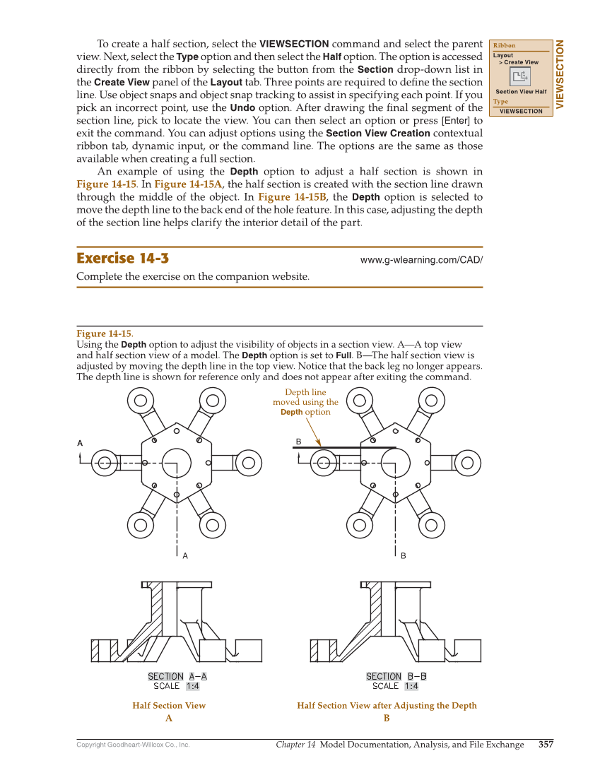
Copyright Goodheart-Willcox Co., Inc. Chapter 14 Model Documentation, Analysis, and File Exchange 357 To create a half section, select the VIEWSECTION command and select the parent view. Next, select the Type option and then select the Half option. The option is accessed directly from the ribbon by selecting the button from the Section drop-down list in the Create View panel of the Layout tab. Three points are required to defi ne the section line. Use object snaps and object snap tracking to assist in specifying each point. If you pick an incorrect point, use the Undo option. After drawing the fi nal segment of the section line, pick to locate the view. You can then select an option or press [Enter] to exit the command. You can adjust options using the Section View Creation contextual ribbon tab, dynamic input, or the command line. The options are the same as those available when creating a full section. An example of using the Depth option to adjust a half section is shown in Figure 14-15. In Figure 14-15A, the half section is created with the section line drawn through the middle of the object. In Figure 14-15B, the Depth option is selected to move the depth line to the back end of the hole feature. In this case, adjusting the depth of the section line helps clarify the interior detail of the part. Exercise 14-3 www.g-wlearning.com/CAD/ Complete the exercise on the companion website. VIEWSECTION Ribbon Layout Create View Section View Half Type VIEWSECTION A A A B B Depth line moved using the Depth option A Half Section View B Half Section View after Adjusting the Depth Figure 14-15. Using the Depth option to adjust the visibility of objects in a section view. A—A top view and half section view of a model. The Depth option is set to Full. B—The half section view is adjusted by moving the depth line in the top view. Notice that the back leg no longer appears. The depth line is shown for reference only and does not appear after exiting the command.