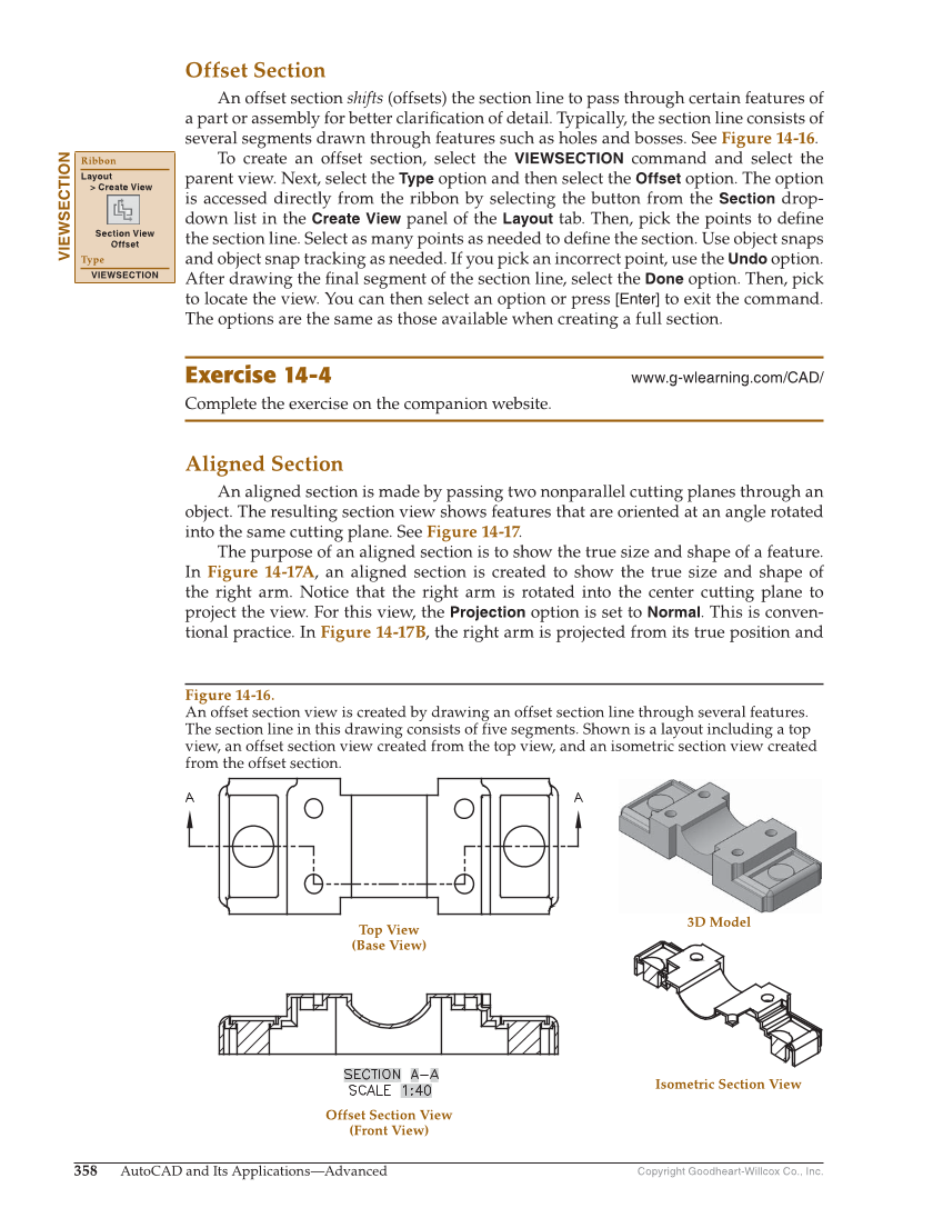
Copyright Goodheart-Willcox Co., Inc. 358 AutoCAD and Its Applications—Advanced Offset Section An offset section shifts (offsets) the section line to pass through certain features of a part or assembly for better clarifi cation of detail. Typically, the section line consists of several segments drawn through features such as holes and bosses. See Figure 14-16. To create an offset section, select the VIEWSECTION command and select the parent view. Next, select the Type option and then select the Offset option. The option is accessed directly from the ribbon by selecting the button from the Section drop- down list in the Create View panel of the Layout tab. Then, pick the points to defi ne the section line. Select as many points as needed to defi ne the section. Use object snaps and object snap tracking as needed. If you pick an incorrect point, use the Undo option. After drawing the fi nal segment of the section line, select the Done option. Then, pick to locate the view. You can then select an option or press [Enter] to exit the command. The options are the same as those available when creating a full section. Exercise 14-4 www.g-wlearning.com/CAD/ Complete the exercise on the companion website. Aligned Section An aligned section is made by passing two nonparallel cutting planes through an object. The resulting section view shows features that are oriented at an angle rotated into the same cutting plane. See Figure 14-17. The purpose of an aligned section is to show the true size and shape of a feature. In Figure 14-17A, an aligned section is created to show the true size and shape of the right arm. Notice that the right arm is rotated into the center cutting plane to project the view. For this view, the Projection option is set to Normal. This is conven- tional practice. In Figure 14-17B, the right arm is projected from its true position and VIEWSECTION Ribbon Layout Create View Section View Offset Type VIEWSECTION Top View (Base View) 3D Model Offset Section View (Front View) Isometric Section View Figure 14-16. An offset section view is created by drawing an offset section line through several features. The section line in this drawing consists of five segments. Shown is a layout including a top view, an offset section view created from the top view, and an isometric section view created from the offset section.